
1. What Is Wireless Mesh in UniFi?
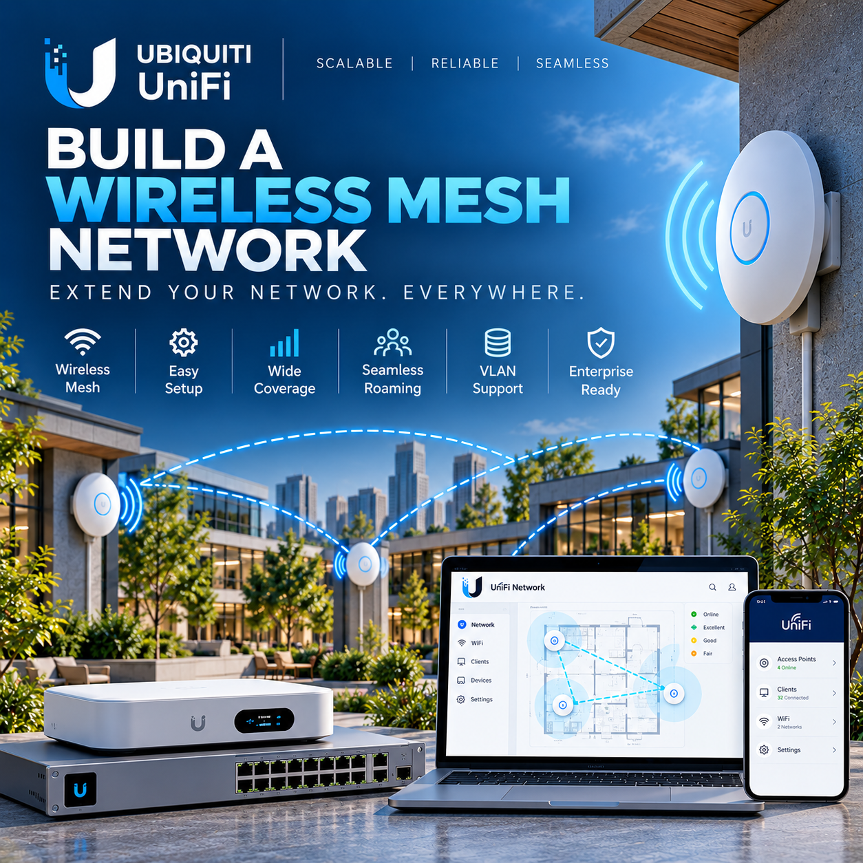
UniFi wireless meshing extends the LAN through a radio uplink between APs. A client joins a normal WiFi SSID; its traffic reaches the wired network through the mesh AP and its parent. The SSID is the user access network, while Wireless Uplink is the AP-to-AP transport.
This runbook is for Network Administrators and System Engineers deploying three compatible UniFi APs under one UniFi Network Application. It describes a verified documentation baseline and a target-side acceptance procedure; no live UniFi hardware measurements are claimed.
2. When to Use Mesh and When to Use Ethernet
Use mesh to reach a small coverage gap where pulling Ethernet is impractical, provided a suitable parent link exists. Cable APs for predictable capacity, busy offices, latency-sensitive applications and permanent infrastructure. Wireless coverage alone does not establish that a site has enough capacity.
Each retransmission consumes radio airtime. Ubiquiti warns of roughly halved throughput per wireless hop; treat this as a planning warning, not a guaranteed benchmark. Compare measured application goodput with your wired baseline and test both children together.
3. Parent AP and Mesh AP Architecture
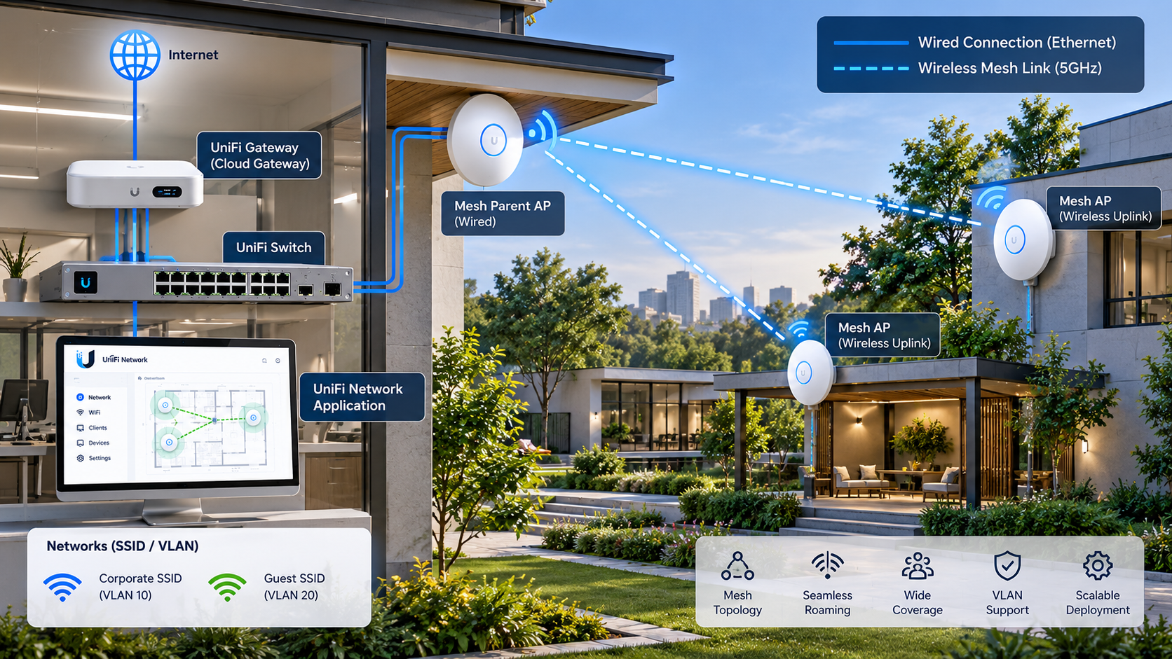
UniFi Network Application: manages all three APs
Gateway (routing + DHCP) -- Ethernet -- AP-PARENT
                                      |
                                      +~~ wireless ~~ AP-MESH-01
                                      +~~ wireless ~~ AP-MESH-02
Shared user SSID on all three APs; one wireless hop per child.
Wireless APs still require local electrical power / compatible PoE.
The Cloud Gateway may host Network, or a separate supported Network host may manage an independent Gateway. The parent has a real Ethernet path to the Gateway. Both children should connect directly to that parent. A chain through another child adds a hop and shares that child’s upstream capacity.
The APs bridge user traffic; Gateway DHCP allocates addresses in the selected user network. UniFi Network is the management plane, not the DHCP relay or a per-packet user-traffic tunnel endpoint. Keep the AP management network reachable independently of guest restrictions.
4. Prerequisites
- Confirm mesh support for the exact AP models and firmware. Do not infer support merely from a UniFi product name; Standalone Mode does not provide this managed mesh deployment.
- Use supported Network and AP releases; record versions, save a Network backup and document the current port/VLAN settings before changes.
- Provide model-compatible PoE and power budget for each AP. For a wireless child, the injector LAN/data input stays disconnected from the LAN; its PoE output powers the AP.
- Verify the parent’s switch port, management DHCP/DNS and access to Network; reserve management addresses if your operational policy requires predictable IPs.
- Select the correct regulatory country and legal channels. Survey parent-to-child locations before final mounting, with doors closed and normal sources of interference active.
5. Adopt the Devices
- Connect and power AP-PARENT through Ethernet. In UniFi Devices, select the discovered AP and adopt it; wait until it is Online and provisioning completes.
- For a controlled rollout, temporarily wire each child to the same management network, adopt it, apply firmware updates and name it AP-MESH-01 or AP-MESH-02.
- Apply global meshing and parent roles below. For the planned conversion, provision Mesh Connect on the child while management access is still available, then promptly disconnect its LAN data uplink and retain PoE power. Do not leave it operating with Mesh Connect and a wired uplink. Wait for an Online wireless uplink before moving it to its final location.
- Wireless adoption is also supported: enable global meshing and the parent role, power a factory-default compatible child near the parent, and adopt it when discovered. If it cannot be discovered, use temporary Ethernet to isolate adoption from RF issues.
The general Device Adoption page currently names Mesh Connect on the uplink AP. The dedicated mesh guide explicitly assigns Mesh Parent to the uplink source and warns against Mesh Connect on a wired AP. This runbook follows that role-specific guide; do not enable Mesh Connect on the wired parent to work around discovery.
6. Create the Shared SSID
In Settings → WiFi, create a WiFi, choose its SSID and authentication, select the intended Network and include all three APs in its broadcasting selection. Save and verify the same SSID, security and user network on each AP. Start with compatible security defaults; verify older devices before changing authentication settings.
One ordinary SSID maps to one VLAN. The base scenario uses one shared Corporate SSID. Guest segmentation can add a separate Guest SSID mapped to its own VLAN. A single SSID with different user VLANs needs supported PPSK or RADIUS assignment and is a separate authentication design, not an automatic result of mesh.
7. Enable Wireless Meshing
Settings → WiFi → Wireless Meshing → EnableEnable the site-level setting and apply changes. Verify device provisioning finishes. The paths here follow the current Help Center interface labels; option grouping can differ with Network release and AP model. If the setting is absent, check model support, permissions and the installed release before using older UI instructions.
8. Configure the Wired Mesh Parent
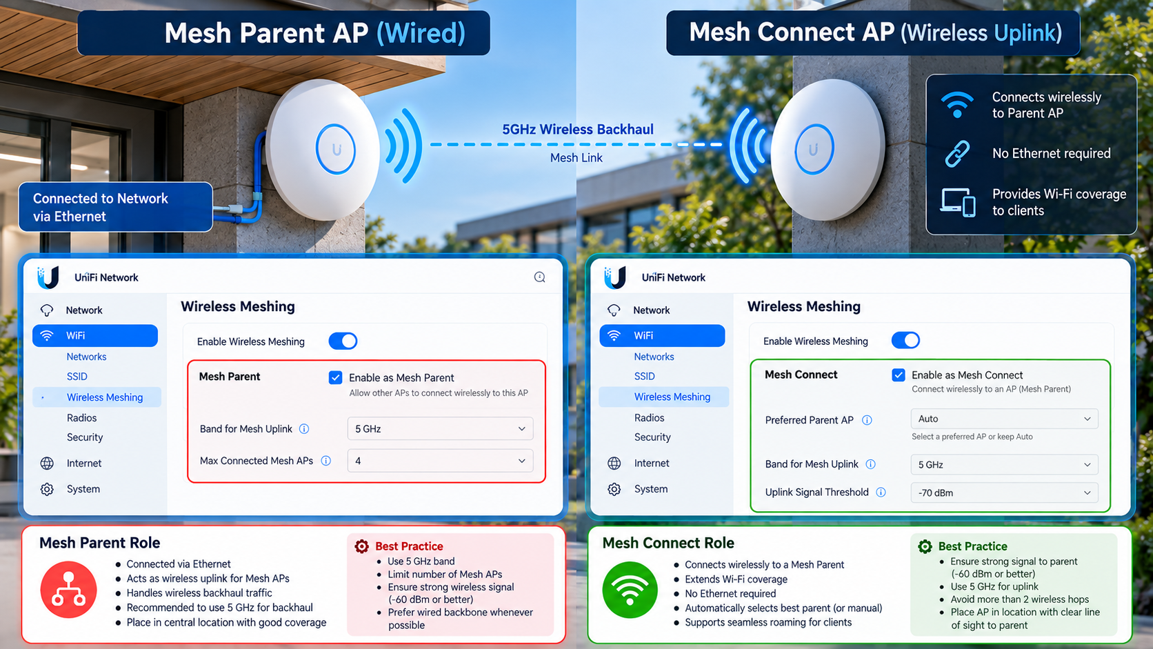
The supplied illustrations explain the roles; their interface panels are conceptual, not verified screenshots of the current application. Follow the documented GUI paths in the text. Do not apply illustrated fields such as a parent limit, preferred-parent selector or uplink threshold without verifying that the installed release actually provides them.
UniFi Devices → AP-PARENT → Settings → Mesh Parent → Enable
UniFi Devices → AP-PARENT → Settings → Mesh Connect → Disable
Confirm Ethernet uplink and actual Gateway reachability first. Mesh Parent allows downstream APs to use this AP as an uplink source. In this one-parent design, enable this role on AP-PARENT. Mesh Connect stays off while it has a wired uplink.
9. Configure Mesh Connect on Wireless APs
UniFi Devices → AP-MESH-01 → Settings → Mesh Connect → Enable
UniFi Devices → AP-MESH-02 → Settings → Mesh Connect → Enable
For this direct-star topology, leave Mesh Parent disabled on both children to avoid using them as intermediate parents. Keep each child powered with no LAN data uplink. Validate the parent identity after provisioning. When converting a child back to Ethernet, disable its Mesh Connect role and recheck the topology.
10. Verify Wireless Uplink
Open UniFi Devices and select each child. Inspect its displayed uplink/connection details and confirm a wireless connection to AP-PARENT, Online state and no intermediate AP. Cross-check Topology; do not treat a diagram alone as proof. Record parent name/MAC, backhaul band, channel and reported signal where the model exposes them.
Join the shared SSID near each child, verify its serving AP in the client details, obtain a Gateway DHCP lease and reach the intended services. This checks both AP management and the client data path; an Online AP alone is not an acceptance test.
11. RF Design and 5 GHz Backhaul
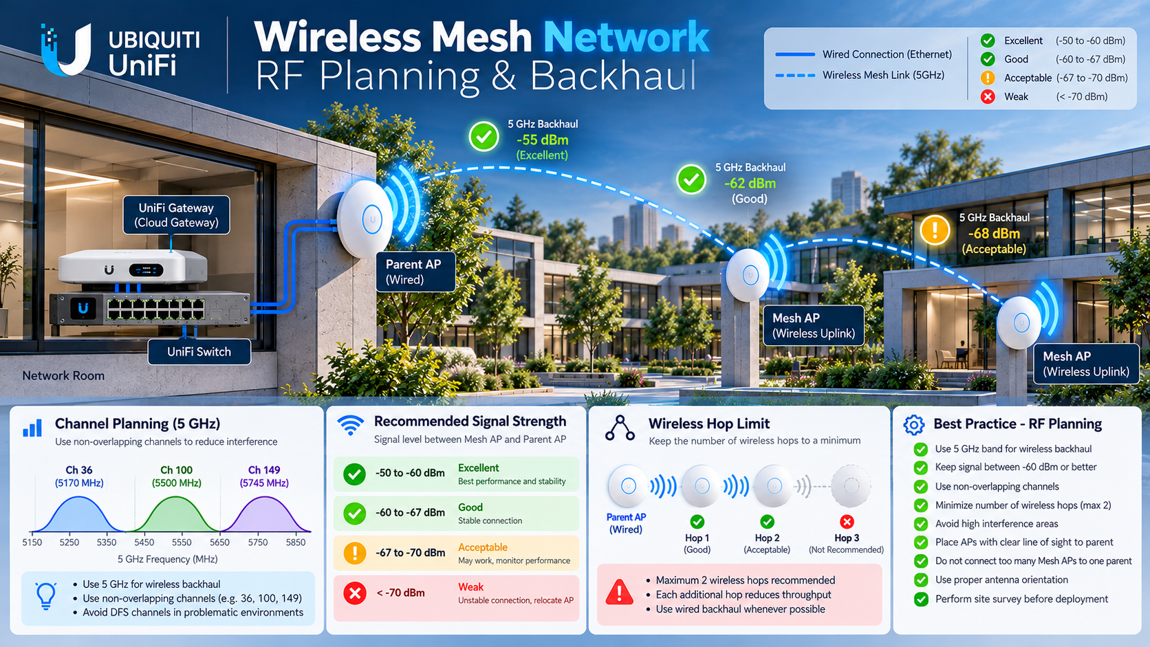
The RF illustration also shows a chained extension and sample channels/signal labels. The deployment in this runbook uses two direct children instead. Its acceptance target remains -60 dBm or better; pictured channel numbers and weaker signal categories are not configuration prescriptions.
UniFi mesh primarily uses 5 GHz. Plan and verify that backhaul on supported equipment; do not assume a dedicated backhaul radio or a configurable 6 GHz uplink on every model. The radio can carry both clients and backhaul, so a good client PHY rate does not guarantee spare upstream airtime.
Locate a child inside reliable parent coverage, before the dead zone. Test mounting height, orientation and obstructions with the final installation conditions. Increasing transmit power alone cannot fix interference, blocked paths or an unbalanced link.
12. Channel Planning
Use UniFi Devices → select AP → AirView → Environment → Airtime Scan when supported. A Full scan interrupts clients on that radio, so schedule it. Record noise and utilization, not just nearby SSID counts. Change one RF variable at a time and repeat the same load test.
For an office baseline, use 20 MHz on 2.4 GHz and assess 40 MHz on 5 GHz; test 80 MHz only where survey and load justify it. Adjust radios in Radios → select radios → Edit Radios or UniFi Devices → select AP → Settings. These are starting choices, not universal throughput settings.
A wireless uplink must use a channel compatible with its parent. Do not assign unrelated 5 GHz channels to members sharing that backhaul as if they were independent wired APs. Reuse planning across wired cells remains useful; verify the actual mesh channel after every change. Use legal non-overlapping 2.4 GHz channels for the country; 1/6/11 is the usual 20 MHz plan.
DFS can offer quieter spectrum, but radar detection may force channel changes and disrupt the backhaul. Validate regional and client/AP compatibility and inspect events when a link drops. Do not prescribe a fixed DFS channel without a site survey.
13. RSSI and Signal Strength
Target parent-to-child RSSI at -60 dBm or better: -55 dBm is stronger than -60 dBm, and -70 dBm is weaker. Measure the AP uplink, not a phone’s client signal. Capture readings under normal occupancy and load; a single quiet-time sample cannot establish link stability.
Assess retries, channel use, latency and loss alongside RSSI. Client Minimum RSSI is a different setting that disconnects weak clients; it does not strengthen the mesh uplink. Avoid applying a blanket threshold to conceal a placement problem.
14. VLANs Across the Mesh
- In Settings → Networks, create Corporate and, if needed, Guest virtual networks on the UniFi Gateway. Use approved VLAN IDs, distinct non-overlapping subnets and Gateway DHCP scopes; check exclusions and available leases.
- In Settings → WiFi, map each SSID to its intended Network. The supported mesh path bridges the selected client network; it does not create a new DHCP server on each child.
- On the parent’s upstream switch port, use Ports → select port → Native VLAN / Network and Tagged VLAN Management. Preserve the actual management network and allow Corporate/Guest tags along every upstream link.
- Do not set a tagged SSID network as the AP port’s native network; Ubiquiti warns that this breaks connectivity except for its VLAN 1 case. For a separate management VLAN, align AP IP Settings → Network Override with the intended tagged management path before changing it.
- For Guest, enable Network Isolation in Settings → Networks and review Client Device Isolation in WiFi settings if client-to-client separation is required. Verify access policy through actual guest clients; a VLAN name alone provides no security boundary.
Validate each VLAN from the wired parent and from both children: expected subnet, Gateway, DNS, permitted internal services and blocked guest-to-corporate access. If only wireless clients fail, compare the child’s SSID/network assignment and uplink; if all APs fail, inspect Gateway DHCP and upstream tagging first.
Client Device Isolation covers clients on the same AP. For separation across APs, assess supported switch Device Isolation (ACL) and the complete forwarding path, including wireless children. Test guest-to-guest access on the same AP and across different APs; do not claim complete isolation from the WiFi toggle alone.
Ubiquiti: Creating Virtual Networks (VLANs)
15. Client Roaming Between APs
Roaming is a client decision. A common SSID, consistent authentication and the same user VLAN permit movement without deliberately changing the subnet, but do not guarantee a lossless handoff. Coverage overlap and usable upstream capacity matter on every AP.
Review Settings → WiFi → select SSID → Advanced for Fast Roaming and BSS Transition. Test the actual client fleet, especially voice handsets and older devices, before rollout. Walk the intended route during an active call and continuous ping; correlate the serving AP change with loss and latency. Mesh reconnection is an AP backhaul event, not client roaming.
16. Performance Testing and Acceptance
Place a test server on the wired LAN and first measure wired client-to-server performance. Repeat near the parent, near each child and with both children active. Keep server, client, test duration and application settings constant. An internet speed test also measures ISP and WAN conditions, so it cannot isolate mesh performance.
# On the wired test server (iperf3 installed):
iperf3 -s

# On a LAN/WiFi test client: replace the example with the server IP
iperf3 -c <wired-server-ip> -t 30
iperf3 -c <wired-server-ip> -t 30 -R

# Windows client: replace with the actual Gateway address
ping -n 100 <gateway-ip>
ipconfig /all
Angle-bracket values are placeholders, not runnable addresses. Install iperf3 separately, allow its TCP 5201 only between the test endpoints and run one test at a time for baseline measurements. The commands are client/server diagnostics, not a UniFi AP CLI configuration. Reverse mode measures the opposite traffic direction.
Record per child: parent identity, hop count, RSSI, channel/width, connected users, goodput in both directions, loss, latency distribution and roaming interruptions. Agree application throughput and latency targets before release. As design gates, require both children on the intended one-hop parent, an approximately -60 dBm-or-better link under normal conditions, correct leases on every VLAN and guest policy passing. Repeat under expected concurrent load.
These commands require iperf3, not UniFi shell access. They are based on the upstream iperf3 invocation; practical acceptance targets are engineering recommendations and must be agreed for this site.
17. Troubleshooting
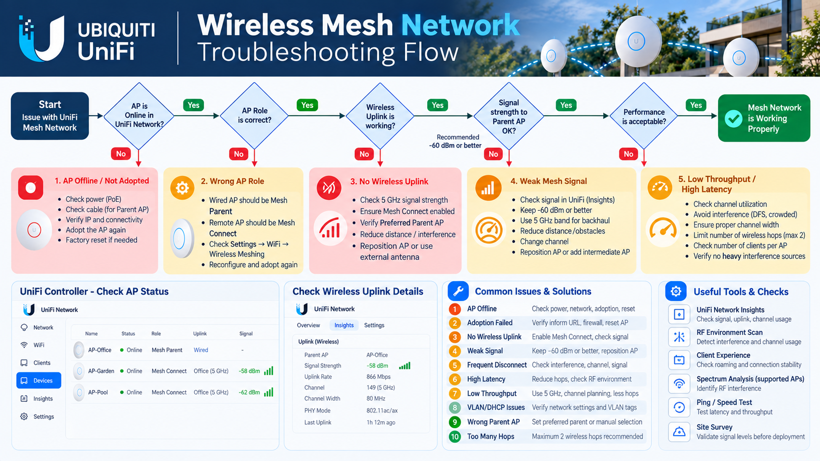
AP Offline
Check PoE LEDs, injector power, parent Ethernet and Gateway reachability. Compare the last event with power or switch changes. Bring the child near the parent; if still offline, temporarily wire it to check management connectivity before RF tuning.
Adoption Failed
Verify discovery on the intended management network, previous controller ownership, supported firmware and access to Network. Use temporary Ethernet and finish adoption near the parent. Factory reset only after confirming ownership and preserving required configuration.
Isolated AP
An AP can be visible through another AP while unable to reach Network on its management VLAN. Check recent VLAN/firewall changes and move it closer. If recovery fails, follow Ubiquiti’s reset, UniFi Devices → AP → Settings → Remove, re-adopt sequence; temporary wiring and firmware update are the next recovery path.
Weak Mesh Signal
Read parent-link RSSI, not client RSSI. Move the child toward the parent or remove obstructions, then retest noise and load. If the -60 dBm design target cannot be met, add a wired parent nearer the area or install Ethernet.
Frequent Disconnect
Identify whether only a client roams/drops or the AP uplink disconnects. Correlate timestamps with DFS/radio changes, PoE restarts and firmware events. Restore the last known RF settings and stage firmware changes one AP at a time.
High Latency
Compare ping to the local Gateway and wired server with WAN latency. Test idle and busy conditions; inspect airtime, retries and concurrent child traffic. Reduce contention or wire the affected AP instead of masking a loaded backhaul with a WAN setting.
Low Throughput
Compare local goodput on parent versus each child, both directions. Check client band/capability, hop count, channel width, parent Ethernet speed and load. A displayed PHY rate is not application throughput; widening a congested channel can make the result worse.
Wrong Parent AP
Confirm the actual upstream AP in device details. In this three-AP design, allow Mesh Parent only on AP-PARENT and keep it off on both children. Improve placement and verify selection again. Do not assume every release offers a manual parent-lock control.
Too Many Wireless Hops
Trace every AP to Ethernet. Prefer one hop here and cap the design at two wireless hops; move the child, remove intermediate parent roles or add wired APs. A two-hop cap is not a performance guarantee or a reason to design an avoidable chain.
DHCP / VLAN Problems
If the AP is Online but clients get no lease or a wrong subnet, compare SSID Network, native/tagged port settings, AP management override and DHCP scope. Test the same VLAN at the parent; fix the first failing segment. Validate DNS and guest policy after a correct lease is obtained.
Enterprise Design Recommendations
The following are engineering recommendations derived from the documented RF and mesh limitations. A small office can use one wired parent and two direct children for modest traffic after a survey and load test. It accepts a shared bottleneck and a parent failure affecting both children; document that service limitation.
An enterprise design starts with wired backhaul per AP, capacity and coverage surveys, switch PoE budgets, protected power and monitored management. Treat mesh as an exception with a named owner, measured capacity and a plan to cable it. For a high-density or voice-critical floor, assess airtime and concurrent applications rather than purchasing more children for the same parent.
Separate management, Corporate and Guest policies. Evaluate enterprise authentication/RADIUS, logging and access control against organizational requirements. Monitor parent loss, repeated reconnects, signal degradation, DHCP scope usage and load. Test recovery and changes in a maintenance window; do not assume mesh automatically delivers deterministic failover or controller redundancy.
Troubleshooting Checklist
- □ Check power and parent Ethernet before resetting an AP.
- □ Distinguish AP management failure from client data-path failure.
- □ Record the real parent, uplink band, RSSI and wireless hop count.
- □ Correlate disconnects with RF/DFS, power and configuration events.
- □ Check SSID-to-Network mapping, management reachability, VLAN tags and DHCP leases.
- □ Compare local tests at the parent and both children under the same load.
- □ Use temporary Ethernet to recover access; preserve evidence before reset/re-adoption.
Best Practices Checklist
- □ Prefer wired backhaul; deploy mesh where cabling is impractical.
- □ Aim for -60 dBm or better between child and parent.
- □ Prefer one wireless hop and do not design more than two.
- □ Avoid too many children on one parent; size by measured concurrent load.
- □ Survey interference and verify the supported 5 GHz backhaul.
- □ Keep Mesh Connect off on APs with wired uplinks.
- □ Verify Corporate/Guest DHCP, security, roaming and application performance before release.
- □ Save versions, backups, baseline results and a recovery plan.
Introduction
Configuration and Validation
Security Considerations
Production safety
- Do not expose management interfaces or databases to the public Internet.
- Store passwords, tokens, and private keys outside the article and source repository.
- Patch dependencies, restrict administrative access, and retain audit logs.
Conclusion
For this site, deploy one Ethernet parent with Mesh Parent enabled and two directly connected wireless children with Mesh Connect enabled. Confirm DHCP and VLAN forwarding end to end, then accept the design only after RF, simultaneous load and roaming tests pass. Where those results do not meet the application requirement, extend the wired network.
FAQ
Do wireless APs need power?
Yes. No Ethernet data uplink does not mean no power cable. Use compatible PoE or the model’s supported power method.
Are Mesh Parent and Mesh Connect the same?
No. Mesh Parent serves downstream APs; Mesh Connect permits an AP to uplink wirelessly. Keep Mesh Connect disabled on a wired AP.
Does one SSID create the mesh?
No. The client SSID and the AP wireless uplink are separate configurations; both must be checked.
Where does DHCP run?
On the Gateway for each configured user network. A mesh child bridges traffic; it does not need a separate DHCP server.
Can Corporate and Guest use VLANs?
Yes, with supported APs, correct SSID mapping and permitted upstream VLANs. Use distinct SSIDs for simple static assignment, or design supported dynamic assignment separately.
Is two hops a recommended default?
No. It is the documented planning ceiling. This scenario should use one hop for each child.
Can I force a dedicated 5 GHz backhaul on any AP?
Do not assume a dedicated radio or a universal control. UniFi mesh primarily uses 5 GHz; verify the model and its actual uplink.
Does a shared SSID guarantee uninterrupted roaming?
No. The client selects its AP. Validate coverage, authentication compatibility and real call/session continuity.
Official References
GUI paths and roles checked against Ubiquiti Help Center on 7 October 2026. Verify labels and capability on the installed Network release and exact AP model. The operational test sequence and enterprise recommendations are site engineering guidance; numerical throughput promises are intentionally absent.
Ubiquiti: Optimal Wireless Mesh Networks
Ubiquiti: Creating UniFi WiFi SSIDs
Ubiquiti: WiFi Connectivity and Latency
Ubiquiti: Maximizing Wireless Speeds
Ubiquiti: Creating Virtual Networks (VLANs)
Ubiquiti: Switch Port VLAN Assignment