
Introduction
This guide explains MikroTik RouterOS 7: VXLAN Setup Step by Step in a production-aware way, including the design choices, implementation checks, and operational safeguards that matter for MikroTik environments.
Before touching the routers
Use two spare routers or CHR instances with RouterOS 7.9 or newer for this lab. A maintained stable release is preferable. Commands are for an empty lab, not a production default configuration. Open WinBox New Terminal and use Safe Mode with Ctrl+X while changing connectivity.
/system resource print
/interface bridge port print
/ip address print
/ip route print
/export file=before-vxlan
Keep the export off the router and secure. Inspect ether1 and ether2 first: ether1 must be a routed underlay port, ether2 a dedicated lab LAN port. If either is already in a bridge, stop and adapt the design. Do not remove your management interface blindly.
Architecture and Core Concepts
Understand the data flow, trust boundaries, dependencies, and the expected state before changing a live environment. Separate control-plane configuration from data-plane traffic and document every external dependency.
Configuration and Validation
Apply the smallest configuration that satisfies the requirement. Keep environment-specific values in a secret-managed configuration, validate syntax before reload, and verify the result from both the service and client perspectives.
Security Considerations
Production safety
- Do not expose management interfaces or databases to the public Internet.
- Store passwords, tokens, and private keys outside the article and source repository.
- Patch dependencies, restrict administrative access, and retain audit logs.
What are we building?
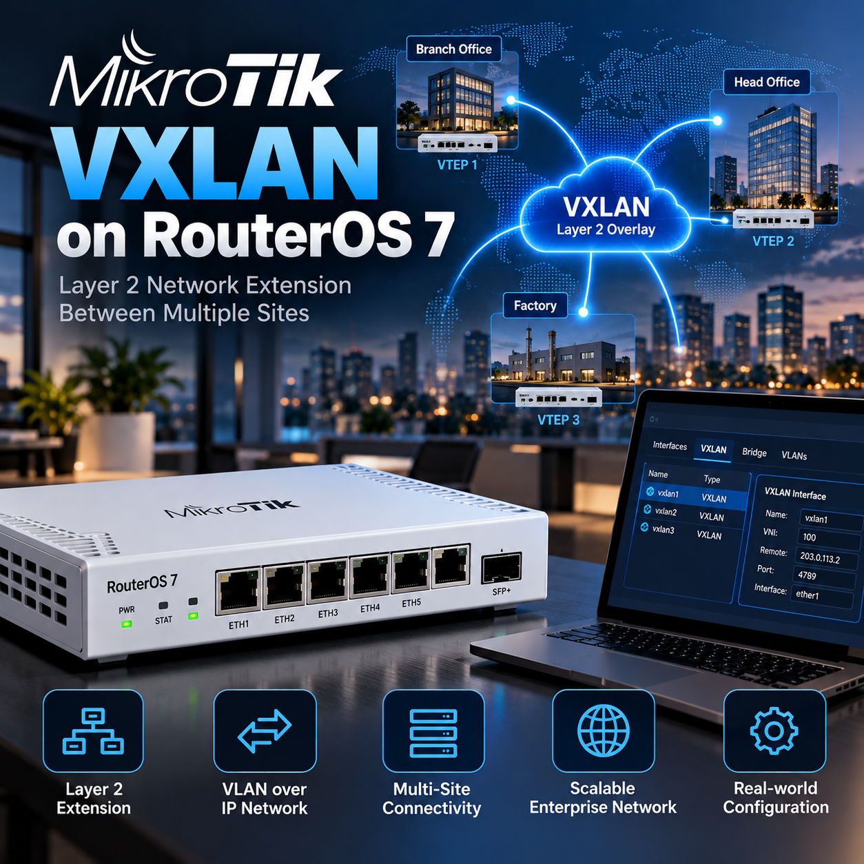
This lab joins two isolated Ethernet LANs across an IPv4 routed link. Use Layer 2 extension only when an application needs it; ordinary access between different IP subnets is usually simpler with routing.
VXLAN carries Ethernet inside UDP. VLAN 10 is a local switching label; VNI 10010 identifies our overlay. Their numbers need not match. Both endpoints must agree on the VNI and UDP port.
Address plan and topology
PC-A 192.168.50.10/24 -- ether2 [R1] ether1 10.20.0.1/30
                                  | IPv4 routed underlay |
PC-B 192.168.50.20/24 -- ether2 [R2] ether1 10.20.0.2/30
Overlay: vxlan10010 / VNI 10010 / UDP 4789
Endpoint MTU: 1450 (untagged IPv4 underlay MTU 1500)
Connect the two ether1 ports directly in this lab. Give the PCs static unique addresses; no gateway is needed for their same-subnet test. Keep DHCP disabled in the lab. In a real routed underlay, replace the endpoint addresses and supply a route in each direction before building the overlay.
Step 1: verify the IP underlay
# R1
/ip address add address=10.20.0.1/30 interface=ether1 comment="VXLAN-LAB-underlay"
/ping 10.20.0.2 src-address=10.20.0.1 count=5
# R2
/ip address add address=10.20.0.2/30 interface=ether1 comment="VXLAN-LAB-underlay"
/ping 10.20.0.1 src-address=10.20.0.2 count=5
Enter each block on its named router; repeat the pings after both addresses exist. A connected /30 route is sufficient here. Fix link, IP or ICMP firewall problems first. Successful underlay ping alone does not prove that UDP or the overlay is working.
Step 2: permit only the peer
For an existing firewall, put the peer-specific accept before any input drop that would match this traffic, and before the rule rejecting traffic outside LAN. Check rule order instead of appending blindly. The following drop applies only to VXLAN UDP on ether1. Preserve management and established-connection rules.
# R1: insert these in this order before matching input drops
/ip firewall filter add chain=input action=accept in-interface=ether1 src-address=10.20.0.2 dst-address=10.20.0.1 protocol=udp dst-port=4789 comment="VXLAN-LAB-peer"
/ip firewall filter add chain=input action=drop in-interface=ether1 protocol=udp dst-port=4789 comment="VXLAN-LAB-deny-other"
# R2: same placement requirement
/ip firewall filter add chain=input action=accept in-interface=ether1 src-address=10.20.0.1 dst-address=10.20.0.2 protocol=udp dst-port=4789 comment="VXLAN-LAB-peer"
/ip firewall filter add chain=input action=drop in-interface=ether1 protocol=udp dst-port=4789 comment="VXLAN-LAB-deny-other"
/ip firewall filter print stats
A static remote VTEP entry is not an access-control rule. VXLAN provides no encryption. Use a trusted private transport; across the Internet, first build an authenticated encrypted path such as WireGuard or IPsec and use its reachable endpoint addresses, then recalculate MTU.
Step 3: configure R1
/interface bridge add name=br-vxlan protocol-mode=rstp mtu=1450 comment="VXLAN-LAB"
/interface vxlan add name=vxlan10010 vni=10010 port=4789 local-address=10.20.0.1 mtu=1450 comment="VXLAN-LAB"
/interface vxlan vteps add interface=vxlan10010 remote-ip=10.20.0.2 comment="VXLAN-LAB"
/interface bridge port add bridge=br-vxlan interface=ether2 comment="VXLAN-LAB"
/interface bridge port add bridge=br-vxlan interface=vxlan10010 comment="VXLAN-LAB"
Only the LAN and VXLAN ports join this bridge. Keep ether1 out of it: the transport must remain a routed network. This basic bridge carries one untagged Ethernet segment.
Step 4: configure R2
/interface bridge add name=br-vxlan protocol-mode=rstp mtu=1450 comment="VXLAN-LAB"
/interface vxlan add name=vxlan10010 vni=10010 port=4789 local-address=10.20.0.2 mtu=1450 comment="VXLAN-LAB"
/interface vxlan vteps add interface=vxlan10010 remote-ip=10.20.0.1 comment="VXLAN-LAB"
/interface bridge port add bridge=br-vxlan interface=ether2 comment="VXLAN-LAB"
/interface bridge port add bridge=br-vxlan interface=vxlan10010 comment="VXLAN-LAB"
Now connect PC-A and PC-B to ether2 on their respective routers. Set both endpoint NICs to MTU 1450 for this lab. Reducing only the tunnel MTU does not tell a bridged PC to stop sending 1500-byte packets.
Step 5: test MTU and end-to-end traffic
For untagged inner Ethernet over IPv4, plan 50 bytes above the inner IP MTU. A 1500-byte path therefore leaves 1450 for the endpoints. Keeping inner MTU 1500 requires at least 1550 across the entire underlay, with suitable Layer 2 capacity. Tags or an additional VPN require more room.
# Linux PC-A: replace enp1s0 with the actual LAN NIC
sudo ip link set dev enp1s0 mtu 1450
ping -c 5 192.168.50.20
ping -M do -s 1422 -c 5 192.168.50.20
# Windows PC-A, elevated terminal: replace Ethernet if needed
netsh interface ipv4 set subinterface "Ethernet" mtu=1450 store=persistent
ping 192.168.50.20
ping -f -l 1422 192.168.50.20
Apply the NIC MTU on PC-B too. In this IPv4 test, 1422 bytes of payload plus 28 bytes of IP/ICMP headers makes 1450. Confirm small and full-size pings, then test the actual application and a file transfer. Allow ICMP on the PC firewall where required.
Optional: map VLAN 10 to VNI 10010
After the basic lab works, the following modifies its existing bridge on BOTH routers. ether2 and vxlan10010 become untagged access ports in VLAN 10. Configure the VLAN table first and enable filtering last. Keep management on a separate interface. This maps one VLAN to one VNI rather than transporting a tagged trunk.
/interface bridge port set [find where bridge=br-vxlan interface=ether2] pvid=10 ingress-filtering=yes frame-types=admit-only-untagged-and-priority-tagged
/interface bridge port set [find where bridge=br-vxlan interface=vxlan10010] pvid=10 ingress-filtering=yes frame-types=admit-only-untagged-and-priority-tagged
/interface bridge vlan add bridge=br-vxlan vlan-ids=10 untagged=ether2,vxlan10010 comment="VXLAN-LAB"
/interface bridge set [find where name=br-vxlan] vlan-filtering=yes
/interface bridge vlan print
For a second isolated segment, allocate another LAN port, VLAN and VXLAN interface with a different VNI and a peer entry on both routers. Do not put unrelated VNIs in an unrestricted bridge. Never create parallel Layer 2 paths without a loop-prevention design.
Operations and safe rollback
Keep one DHCP authority per stretched segment, document the broadcast domain and monitor CPU during real transfers. Hardware acceleration depends on the device, software version and topology; do not infer it from the bridge H flag alone. This guide makes no hardware-offload performance claim.
/interface vxlan disable [find where name=vxlan10010]
/interface bridge port remove [find where bridge=br-vxlan interface=vxlan10010]
/interface bridge port remove [find where bridge=br-vxlan interface=ether2]
/interface bridge vlan remove [find where comment="VXLAN-LAB"]
/interface vxlan vteps remove [find where interface=vxlan10010]
/interface vxlan remove [find where name=vxlan10010]
/interface bridge remove [find where name=br-vxlan]
/ip firewall filter remove [find where comment="VXLAN-LAB-peer"]
/ip firewall filter remove [find where comment="VXLAN-LAB-deny-other"]
/ip address remove [find where comment="VXLAN-LAB-underlay"]
Rollback commands remove only the objects created for this empty lab; inspect matching entries before running. Restore endpoint NIC MTU to its original value (usually 1500) and restore any port membership you changed from the saved export. Keep a separate management session throughout.
Troubleshooting checklist
/interface vxlan print detail
/interface vxlan vteps print detail
/interface vxlan fdb print
/interface bridge host print
/interface bridge port print
/interface bridge vlan print
/ip firewall filter print stats
/tool sniffer quick interface=ether1 ip-protocol=udp port=4789
Start with endpoint reachability. Generate a PC ping while checking UDP counters and the sniffer. No UDP suggests the bridge or peer configuration; one-way UDP suggests routing or firewall order. If packets arrive but PC ARP fails, inspect VNI, bridge membership, PVID and VLAN table. Empty FDB before any traffic is normal.
Small pings working while large packets fail points to MTU. Intermittent access can be duplicate IPs, multiple DHCP servers, or a loop. A running interface flag alone is not proof of remote connectivity. Capture only the traffic needed and stop the sniffer after diagnosis.
Best Practices
- Version-control configuration and review changes.
- Use least privilege and explicit allow-lists.
- Automate repeatable checks and monitor the expected state.
- Test upgrades and restores before production rollout.
Conclusion
A reliable implementation of MikroTik RouterOS 7: VXLAN Setup Step by Step is more than a successful first run. Keep the configuration documented, observable, recoverable, and aligned with the team's change-management process.
Frequently asked questions
Do I install a VXLAN package? No, use the RouterOS interface menu. Does VXLAN encrypt traffic? No. Must VLAN ID equal VNI? No. Is this tested on a live router? No: the command structure was reviewed against official documentation; verify on CHR or spare equipment before production.