
Start with the outage, not the protocol
Imagine two offices, two MikroTik routers and one ERP server at HQ. One encrypted link joins them. I would first write two routes and test the return path. Adding BGP cannot create a second physical path. Now change the design: two ISPs at every branch, two data centers and local Internet breakout. The useful question becomes which failure should withdraw which route, and who is allowed to advertise it.
All organizations below are hypothetical design scenarios. Recommendations assume unique address blocks, supported software, a routed WAN and a team able to operate the chosen protocol. Branch count is a capacity input, not a protocol-selection rule. Commands are documentation-reviewed lab designs, not claimed hardware test results. Documentation snapshot: 5 November 2026; current MikroTik manual identifies itself as 7.26. Older frozen help pages sometimes describe earlier CLI models.
Connected, static and policy routing: what actually installs a route?
A routing protocol exchanges reachability with another router. Connected and static routes do not. The control plane builds the RIB; selected routes become forwarding entries in the FIB. A tunnel carries packets, and encryption protects them. Those jobs may live on the same box, but a successful VPN handshake does not prove that a remote subnet is reachable.
| Mechanism | Classification | Design example and trap |
|---|---|---|
| Connected Routes | Local route source | 10.10.1.1/24 on LAN installs 10.10.1.0/24 while the interface is usable; it says nothing about ERP health. |
| Static Routing | Manual route | At HQ route 10.20.0.0/24 to the branch tunnel IP; add the HQ subnet return route at the branch. |
| Default Routing | Prefix 0/0 or ::/0 | A spoke can send all corporate traffic to HQ if Internet breakout is central. A local Internet default needs specific corporate routes. |
| Floating Static Routes | Preference mechanism | Backup route has a worse distance. It activates after the primary becomes ineligible, not merely because an application times out. |
| Recursive Static Routing | Next-hop resolution | Resolve a probe address through ISP1 and make the corporate route depend on that probe. Pin probe /32 to ISP1 or the backup may make it falsely healthy. |
| ECMP | Forwarding capability | Two equal routes can share flows by hashing. One TCP flow normally uses one member; unequal capacity and stateful firewalls complicate active/active. |
| PBR | Policy override | Send guest VLAN through ISP2 using source policy. A routing mark can override a good main-table route; document return traffic and FastTrack exemptions. |
| VRF Routing | Separate routing tables | OT and IT may both use 10.0.0.0/24 in separate VRFs. Shared services require deliberate route leaking plus firewall rules. |
| Route Tracking | Failure detection/action | An IP SLA/object track or a RouterOS gateway check makes a static route conditional. Test remote reachability, not only the modem. |
RIP and EIGRP: the distance-vector family has more than one behavior
RIP neighbors exchange destination and distance rather than a full topology. RIPv1 broadcasts classful IPv4 routes and cannot carry subnet masks; VLSM and discontiguous designs expose that limit. RIPv2 carries masks and route tags, normally uses 224.0.0.9 on UDP 520, and supports authentication extensions. Both use hop count: 15 is reachable, 16 is infinity. A 1 Gb/s link and a congested radio can look equally attractive if their hop counts match.
Split Horizon avoids advertising a route back where it was learned. Poisoning marks it unreachable; poisoned reverse sends infinity back explicitly. Triggered updates help, but periodic exchange and timers still make some failures slow. Neither mechanism eliminates every transient loop in a changing topology. RIPv2 can summarize where the implementation permits; careless auto-summary can hide subnet detail. A legacy controller speaking only RIP is a reason for a small, filtered compatibility edge, not for extending RIP across a new WAN.
RIPv2: metric, updates and loop controls
RIPng carries IPv6 prefixes using UDP 521 and link-local neighbors, normally ff02::9. Its hop limit remains 15; IPv6 does not fix its scale. It does not reuse the RIPv2 authentication field; security must come from the applicable IPv6/IPsec design and implementation. Treat summarization, authentication and ECMP as implementation checks rather than assuming IPv4 and IPv6 feature parity.
EIGRP is an advanced distance-vector protocol using DUAL, not a link-state protocol. After initial synchronization, changes are incremental and bounded by topology and query behavior. Its usual composite metric uses minimum bandwidth and cumulative delay; K-values must agree. Hop count exists as a limit but is not the default route-selection metric. A feasible successor satisfying the feasibility condition can be used without a diffusing computation; without one, queries may expand and convergence takes longer. Stub spokes and summaries bound those queries.
DUAL and EIGRP: Informational RFC, not an IETF Standards Track protocol
EIGRP for IPv6 uses the same DUAL approach with IPv6 neighbors and an explicit router ID. Authentication algorithms, named mode, wide metrics and address-family features depend on IOS/XE release. Split Horizon matters on multipoint spokes: disabling it blindly may exchange unwanted spoke routes. I would retain a healthy Cisco EIGRP domain when its team understands query boundaries, but choose OSPF or BGP at a MikroTik boundary. An openly published specification does not mean RouterOS implements EIGRP.
OSPF and IS-IS: both run SPF, but their boundaries differ
In OSPFv2, Hello discovers neighbors; matching area, authentication, timers and network type permit adjacency. Routers synchronize an area LSDB, flood changes and run SPF over accumulated interface costs. A broadcast segment elects DR/BDR; two DROther routers can remain 2-Way normally. A point-to-point link has no DR election. Cost is configured or derived from a reference bandwidth, not measured latency. A lossy radio does not automatically become expensive.
An OSPF area belongs to interfaces; an ABR joins areas to backbone area 0 and can summarize between areas. Routers inside one area need consistent topology information, so an ordinary intra-area prefix filter is not a safe arbitrary reachability policy. An ASBR introduces external routes. Summaries reduce detail but can hide a failed more-specific; a discard route and a valid alternate path must be considered. Area boundaries contain topology flooding, not all external-route activity or security risk.
OSPFv2 adjacency, LSAs and areas
OSPFv3 uses IPv6 link-local communication and separates addressing from topology. Base OSPFv3 serves IPv6; IPv4 address families are an extension and require platform support. Instance IDs help run multiple instances on a link. Authentication is not simply the OSPFv2 password syntax: IPsec or an authentication-trailer implementation must be checked on both ends. A working OSPFv2 neighbor does not validate IPv6 firewalling, ICMPv6 or next-hop scope.
IS-IS began with CLNP; Integrated IS-IS adds IP reachability. IIH discovers neighbors, LSPs carry topology in TLVs, CSNP/PSNP help synchronize databases and SPF selects paths by metric. IS-IS control packets run directly over supported link layers rather than TCP/IP. A NET identifies the router. A broadcast LAN elects a DIS per level, with no OSPF-style backup DIS. IPv6 reachability uses extensions; wide metrics avoid the old narrow-metric constraints.
Integrated IS-IS and IP reachability
The architectural difference matters at a regional boundary. An IS-IS router belongs to an area; L1 serves that area and a connected L2 backbone joins areas through L1/L2 routers. An L1 router may use an attached L1/L2 router for destinations outside its area; selective leaking changes that behavior. This is not OSPF area 0 with renamed fields. I would choose IS-IS for a supported provider-style core with an experienced team, and OSPF for a mixed branch estate whose operators already troubleshoot OSPF. Both can scale; physical design, LSP/LSA rate, timers, CPU and failure boundaries decide the result.
BGP: define who may announce what before bringing up the session
BGP-4 is path-vector routing over TCP 179. eBGP connects different ASNs; iBGP distributes paths inside an AS. AS-PATH helps prevent AS-level loops, but does not prevent every forwarding loop. An ASN identifies a routing policy domain, not a branch license. Private ranges are 64512–65534 and 4200000000–4294967294; do not export them unintentionally to the public Internet. Public multihoming needs provider agreement and appropriate public addressing/ASN arrangements. A private WAN can use private ASNs without an Internet full table.
For branch policy, I normally start with exact import/export allowlists. Local Preference selects the preferred exit within the AS; higher wins. AS-PATH length is another selection input. MED suggests an ingress preference and is commonly compared between paths from the same neighboring AS; lower wins under those rules. Communities label intent, but do nothing until a router or provider policy acts on them. Next-Hop must resolve: an Established session with an unreachable next hop still cannot forward the prefix. Selection order and proprietary attributes differ by implementation.
BGP-4 reachability and path attributes
iBGP scaling, MP-BGP and EVPN
An ordinary iBGP speaker does not relay a route learned from one iBGP neighbor to another. A full mesh or Route Reflectors solve distribution; RRs do not have to forward the user traffic and do not repair next-hop reachability. Use redundant reflectors with a deliberate cluster design. Confederations split a large AS into member ASs while presenting one external AS, but add policy and troubleshooting work. An eBGP branch-to-hub design does not need an RR just because it has 100 branches.
MP-BGP adds address-family reachability, including IPv6 unicast and VPN families. BGP for IPv6 is not a separate path-selection protocol. EVPN is a BGP control plane for Ethernet/IP VPN services; VXLAN or MPLS can be its data plane. It is useful for a supported data-center fabric or a defined VPN service, not automatically for every branch. Negotiate the required AFI/SAFI and verify route types, multihoming, IRB, hardware forwarding and scale on the exact platform. A manual containing EVPN does not promise every EVPN feature.
Leak prevention and convergence
Prefix limits bound a mistake; they do not authorize a prefix. Filter default routes and overly broad aggregates explicitly. Aggregate only space you control, with a discard route and known more-specific failure behavior. On Internet edges use origin validation with a maintained RPKI validator and a documented Valid/Invalid/NotFound policy. RPKI origin validation checks origin authorization, not the entire AS path; it is not a complete route-leak defense. Customer/provider roles and export policy remain necessary.
BGP convergence includes detection, withdrawal, selection and FIB installation. BFD can accelerate detection of a forwarding-path failure when both ends support the mode; it does not test ERP. Aggressive timers over a jittery Internet can create false failures. Graceful Restart may retain stale routes and extend a black hole when forwarding is actually gone. BGP Multipath needs compatible attributes and explicit platform support; it does not make every Established peer an ECMP member. Measure failover with traffic in both directions.
Mesh, constrained devices and historical protocols
| Protocol | Purpose and mechanism | Practical placement |
|---|---|---|
| Babel | Loop-avoiding distance vector, feasibility and sequence numbers; metrics can reflect wireless quality. | Linux babeld/BIRD implementations and OpenWrt packages; verify the installed package. Useful for routed community/edge mesh, not automatically the choice for a Cisco/MikroTik branch fleet. |
| OLSR | Proactive link-state MANET protocol; multipoint relays reduce flooding. | Linux olsrd/OpenWrt where available; dynamic wireless adjacency differs from a fixed point-to-point radio carrying OSPF. |
| OLSRv2 | NHDP neighbor discovery and metric-aware topology with MPR selection; not wire-compatible OLSRv1. | OONF/olsrd2 implementations on supported Linux systems; check image/package resources. A protocol migration needs both ends changed. |
| RPL | IPv6 low-power/lossy routing builds a DODAG toward a root using an objective function and rank. | IoT stacks such as Contiki-NG and compatible border routers, not a general WAN IGP. Parent selection balances link quality, energy and memory constraints. |
| ODR | Cisco On-Demand Routing uses CDP information for stub reachability; not a general full topology protocol. | Specialized Cisco hub/stub designs; ODR is documented in IOS XE 17.x but exact model/image support must be checked. Prefer interoperable static/OSPF/BGP for new mixed fleets. |
| IGRP — Legacy | Cisco classful distance vector, composite metric and periodic updates; predates EIGRP. | Historical context only; no IPv6 or modern VLSM design. Do not deploy it in a new enterprise. |
| EGP — Historical | The old Exterior Gateway Protocol exchanged inter-AS reachability under restrictive topology assumptions. | Replaced by BGP. EGP as a protocol name differs from the category exterior gateway protocols. |
| 802.11s / HWMP / batman-adv | Mesh path selection may operate at Layer 2; a bridged mesh is not an IP routing protocol. | Inspect radio firmware and forwarding layer first. A vendor wireless mesh feature does not imply Babel, OLSR or RPL support. |
RPL for constrained IPv6 networks
Cisco ODR hub/stub design scope
Supporting technologies: put each tool in the right layer
| Technology | Role | Example and boundary |
|---|---|---|
| BFD | Forwarding-path failure detection | Signals a supported routing client to react; not a route advertisement protocol and not application monitoring. |
| VRRP / HSRP / GLBP | First-Hop Redundancy | VRRP is standardized; HSRP/GLBP are Cisco technologies. A virtual LAN gateway survives a router loss; WAN routing and firewall-state continuity remain separate. GLBP also distributes gateway use on supported platforms. |
| MPLS | Label forwarding | A provider can carry L3VPN with labels. MPLS alone does not discover all customer routes or encrypt traffic. |
| LDP | Label distribution control protocol | Usually follows IGP reachability to construct label paths; it is a protocol, but not an IP unicast route-selection replacement. |
| RSVP-TE | TE signaling and reservation | Signals engineered label paths and constraints on supported cores; adds state and operational work. |
| Segment Routing / SR-MPLS / SRv6 | Source/ingress-directed forwarding architecture | SR-MPLS uses segment labels; SRv6 uses IPv6 segment identifiers and behaviors. IGP/BGP/PCE distribute relevant information. IPv6 support alone does not imply SRv6 support. |
| EVPN / VXLAN | VPN control plane / encapsulation | EVPN advertises VPN information; VXLAN carries Ethernet in UDP. A VXLAN bridge with static remote VTEPs is not automatically EVPN. |
| SD-WAN | Overlay and management architecture | Policy, telemetry, orchestration and path selection vary by vendor. It can use BGP or OSPF at boundaries; it is not one interoperable routing protocol. |
| VRF | Routing isolation | Separate RIB/FIB contexts; isolation is incomplete if routes leak broadly or a shared firewall permits everything. |
| Route Redistribution | Route import between sources | Static to OSPF or OSPF to BGP needs an explicit prefix list, metric and tags. Two uncontrolled import points can feed routes back and create loops. |
| Route Filtering | Control-plane policy | Limit advertised/accepted prefixes; this does not replace a data-plane firewall. In an IGP respect topology consistency and legal boundary filtering. |
Protocol comparison: behavior before brand support
These are engineering tendencies, not convergence guarantees or a router sizing table. Convergence is measured from traffic loss to stable forwarding and includes hardware programming. ECMP counts, cryptographic algorithms and scale limits belong to an exact release/model/license. A dash means not applicable, not a missing feature.
| Protocol | Type / status | IPv4 / IPv6 | Metric | Convergence / scale / administration | Policy / ECMP |
|---|---|---|---|---|---|
| Static / Default | Manual / open method | Yes / Yes | Preference + resolution | Tracking-dependent; human change volume is the limit; low until redundancy grows. | Explicit prefix; ECMP implementation-dependent. |
| RIPv1 | Distance vector / historical open RFC | Yes / No | Hop count ≤15 | Timer-driven; small legacy islands; deceptively simple. | Weak policy / implementation-dependent ECMP |
| RIPv2 / RIPng | Distance vector / open standards | v2: Yes/No; ng: No/Yes | Hop count ≤15 | Periodic + triggered; small domains; low administration. | Prefix filtering / implementation-dependent ECMP |
| IGRP | Distance vector / Cisco Legacy | Yes / No | Composite | Historical; not a new design option. | Legacy |
| EIGRP / EIGRP IPv6 | Advanced distance vector / Cisco, RFC Informational | Yes / Yes by AF | Bandwidth + delay normally | Fast with feasible successor; query boundaries matter; medium administration. | Good filtering; equal and supported unequal-cost paths |
| OSPFv2 / OSPFv3 | Link state / open standards | v2 IPv4; v3 IPv6, IPv4 AF extension | Accumulated cost | Detection + SPF + FIB; hierarchical domains; medium/high design effort. | Boundary policy; ECMP supported by implementations |
| IS-IS / Integrated IS-IS | Link state / ISO + IETF extensions | Integrated IPv4; IPv6 extensions | Narrow/wide metric | Strong core scaling with bounded domains; experienced operations. | Level-boundary policy; implementation ECMP |
| BGP-4 / MP-BGP | Path vector / open standards | Yes / IPv6 AF | Ordered attributes | Policy and timer-dependent; large route sets; high operational responsibility. | Rich policy; multipath explicit/version-dependent |
| Babel | Distance vector / open standard | Yes / Yes | Link-quality/cost | Adapts to mesh change; implementation sizing required. | Implementation-specific policy and multipath |
| OLSR / OLSRv2 | Proactive link state / Experimental v1, standard v2 | Both by implementation | v1 hops/extensions; v2 link metric | Mobile mesh; periodic overhead; specialist operations. | Implementation-dependent |
| RPL | DODAG / open standard | No / Yes | Objective function / rank | Constrained IoT scale and memory modes; specialist. | Not WAN multipath equivalence |
| ODR | Cisco specialized stub / CDP-based | IPv4 / No | Stub reachability | Specialized hub/stub, exact image check | Not a general multi-vendor WAN policy design |
| EGP | Historical exterior | IPv4 / No | Historical reachability | Historical context only | Replaced by BGP |
| Family | Authentication | Summarization | Hierarchy | Branch / DC / SP |
|---|---|---|---|---|
| Static | Protect management; no neighbor authentication | Manual aggregate with discard | Manual | Small edge / limited / limited |
| RIP | v1 none; v2 auth extensions; ng IPv6 security design | v1 classful; v2/ng implementation | No areas | Legacy / avoid new fabric / legacy only |
| EIGRP | MD5/HMAC options by platform/release | Interface/manual; query containment | Stub and summary, no OSPF areas | Cisco estate / selected platforms / selected use |
| OSPF | v2 crypto by implementation; v3 IPsec/AT by support | ABR/ASBR boundaries | Area 0, regular/stub/NSSA | Strong / underlay option / IGP option |
| IS-IS | PDU authentication by implementation | At level boundaries with supported policy | L1 / connected L2 | Specialist / core underlay / strong |
| BGP | TCP authentication options + control ACL; not encryption | Explicit aggregation | AS / RR / confederation | Policy WAN / underlay or EVPN / strong |
| Babel / OLSR / RPL | Protocol-specific security extensions/modes; verify stack | Implementation or root-oriented scope | Mesh / MPR / DODAG | Specialized, not ordinary branch/DC/SP default |
Platform support: a release-specific contract
Scope: RouterOS current manual 7.26 on an architecture exposing the feature; Cisco routing-capable IOS/IOS XE 17.x; Nexus 9000 NX-OS 10.5(x). Supported means documented in that scope, not present on every switch, license or older image. Platform-Dependent requires checking the model feature table. Version-Dependent requires checking the exact image and feature subset. Legacy is historical, not a deployment recommendation. Do not turn an absent vendor manual entry into an unsupported global claim.
| Protocol / feature | MikroTik RouterOS | Cisco IOS / IOS XE | Cisco NX-OS | Restriction / evidence |
|---|---|---|---|---|
| Connected / Static / IPv6 Static | Supported (7.26) | Platform-Dependent (17.x) | Platform-Dependent (N9K 10.5) | FIB and VRF scale require model data |
| RIPv1 | Not Supported | Legacy / Platform-Dependent | Platform-Dependent | MikroTik explicitly excludes v1 in its RIP implementation note |
| RIPv2 | Supported (7.26) | Platform-Dependent (17.x) | Platform-Dependent (N9K 10.5) | RIP guide and NX-OS RIP chapter |
| RIPng / IPv6 RIP | Version-Dependent (7.26 CLI afi=ipv6) | Platform-Dependent | Platform-Dependent (RIPng chapter) | Current RIP instance CLI documents IPv6 AF; verify exact deployed image, not RIPv2 parity |
| EIGRP / EIGRP IPv6 | Not Supported (native RouterOS) | Platform-Dependent (17.x) | Platform-Dependent (10.5 EIGRP) | NX-OS EIGRP tunnel interfaces explicitly not supported; AF restrictions apply |
| OSPFv2 / OSPFv3 | Supported (7.26) | Platform-Dependent (17.x) | Platform-Dependent (N9K 10.5) | OSPFv3 IPv4 AF is a separate feature check |
| Integrated IS-IS | Version-Dependent; documented 7.26 | Platform-Dependent | Platform-Dependent (10.5 IS-IS chapter) | Do not say RouterOS v7 has no IS-IS; extensions differ |
| BGP IPv4 / IPv6 / RR | Supported (7.26; !smips CLI condition) | Platform-Dependent (17.x) | Platform-Dependent (N9K 10.5) | BGP instance model differs across v7 releases |
| MP-BGP / EVPN | Version-Dependent; current EVPN guide | Platform-Dependent | Platform-Dependent; separate VXLAN/EVPN guide | Route types, IRB, multihoming and ASIC offload require exact validation |
| MPLS / LDP / L3VPN / VPLS | Platform-Dependent; MPLS manual | Platform-Dependent | Platform-Dependent; do not assume N9K is an MPLS PE | MPLS service/encapsulation support is not identical across these families |
| Babel / OLSR / OLSRv2 / RPL | Not Supported as native unicast engines | Not a blanket IOS XE claim; specialist product/stack required | Not documented in selected unicast guide | External Linux/IoT software is not native router support |
| IGRP / EGP | Not Supported as native listed protocols | Legacy | IGRP Not Supported; EGP not promised | Historical references cannot establish modern support |
| ODR | Not Supported (Cisco CDP-based feature) | Platform-Dependent (IOS XE ODR guide) | Not documented in selected guide | Specialized stub design; no general multi-vendor support |
MikroTik explicitly excludes RIPv1
RouterOS 7.26 RIP IPv4/IPv6 address families
RouterOS BGP architecture conditions
Routing over a WAN: carrier, encryption and adjacency are separate
BGP needs unicast IP reachability to its peer, plus TCP 179 and next-hop reachability. Static needs a usable next hop. OSPF normally uses IP multicast and protocol 89; explicit unicast neighbors on a supported NBMA/point-to-multipoint model are an alternative. EIGRP uses IP protocol 88 and normally multicast hellos, with platform-specific unicast modes. IS-IS needs a compatible link-layer adjacency, not just a reachable IP address. That is why “the tunnel passes ping” is an incomplete compatibility test.
In the matrix, L3 means a routed interface carrying the required IP family. MC means the interface/overlay must actually deliver multicast. L2 means an Ethernet-like service that can carry the necessary frames. Conditional is a design gate, not a promise. EIGRP also requires an EIGRP implementation at both ends; MikroTik cannot become one merely by adding GRE.
| Transport / class | Static / BGP | OSPF / EIGRP | IS-IS / IPv6 | MC / broadcast / interface |
|---|---|---|---|---|
| WireGuard / encrypted L3 | Yes / Yes unicast | Conditional: peer mapping + MC or supported unicast neighbors | No direct L2 / IPv6 yes | No Ethernet broadcast; one peer per interface simplifies OSPF; no automatic MC fan-out |
| GRE / L3 encapsulation | Yes / Yes | Yes with IP MC and compatible routers | Not assumed over IP-only GRE / IPv6 payload platform check | IP multicast yes; Ethernet broadcast no in ordinary L3 GRE |
| GRE over IPsec / protected encapsulation | Yes / Yes | Yes; check crypto selector protects GRE | L2 not assumed / IPv6 payload conditional | GRE supplies multicast, IPsec supplies protection; interface-based |
| IPsec site-to-site / security suite | Depends on route/policy model | Not established by the term IPsec alone | Link layer not supplied / IPv6 implementation | Name alone does not specify interface or MC |
| Route-Based IPsec / VTI model | Yes / Yes when supported | Conditional MC/neighbor support | No direct L2 / IPv6 implementation | Routed interface; vendor VTI interoperability and traffic selectors checked |
| Policy-Based IPsec / selectors | Static selects traffic; BGP endpoints must match selectors | No generic interface adjacency; add GRE if needed | No L2 / IPv6 selectors conditional | No general MC/broadcast service; policies can omit newly learned subnets |
| IPIP / IPIP over IPsec | Yes / Yes | Conditional MC support and explicit design | No L2 / IPv6 depends on tunnel type | IP-in-IP, not Ethernet; IPsec optional protection |
| EoIP / Ethernet overlay | Yes on routed bridge/VLAN / Yes | Yes on appropriate L3 interface | Conditional L2 IS-IS / IPv6 yes | Ethernet broadcast/MC yes; MikroTik-focused, Cisco has no native EoIP interop |
| L2TP/IPsec / PPP + security | Yes / Yes | Conditional PPP interface support | No Ethernet by default / IPv6 PPP support | Routed PPP interface; do not assume BCP/bridge everywhere |
| OpenVPN / TLS VPN | Yes / Yes on supported TUN/TAP | Conditional TUN MC or TAP plus support | TAP conditional L2 / IPv6 version-dependent | Mode, UDP/TCP and cipher support differ across RouterOS versions |
| SSTP / TLS PPP | Yes / Yes | Conditional PPP adjacency | No direct Ethernet / IPv6 stack check | TCP 443 outer transport; TCP-in-TCP can amplify loss stalls |
| VXLAN / L2 UDP overlay | Yes on SVI/IRB / Yes | Conditional L3 interface over service | Conditional L2 control support / IPv6 payload yes | Ethernet BUM via replication/MC; underlay and VTEP support required |
| MPLS L3VPN / provider service | CE-PE static or BGP per contract | OSPF/EIGRP CE-PE only if provider offers it | Not transparent IS-IS / IPv6 VPN service check | No customer L2 broadcast; multicast VPN is a separate service |
| MPLS L2VPN / VPLS / Ethernet service | Yes on CE routed links / Yes | Yes if service carries required packets | Conditional L2 PDU transport / IPv6 yes | VPLS multipoint vs point-to-point pseudowire; BUM/loop controls matter |
| DMVPN / mGRE + NHRP + IPsec | Yes / Yes with design | OSPF/EIGRP possible; phase/topology restrictions | Not generic L2 / IPv6 platform check | Cisco architecture; RouterOS is not a native interoperable DMVPN hub |
| FlexVPN / IKEv2 architecture | Yes / Yes | Conditional VTI/virtual access support | No generic L2 / IPv6 platform check | Cisco IKEv2 framework; ordinary IKEv2 interop is not all FlexVPN features |
| SD-WAN / managed overlay | Static/BGP boundary per product | Boundary integration per product | Not generic IS-IS transport / IPv6 product check | Internal control and multicast replication vendor-dependent |
| Private Fiber / physical medium | Yes with L3 interfaces | Yes with compatible interface | Yes on compatible L2 / IPv6 yes | Fiber itself defines neither topology nor encryption |
| Point-to-Point Radio / link | Yes / Yes | Yes over transparent/routed compatible link | Conditional bridge L2 / IPv6 supported link | Loss/jitter and radio bridging/filters matter |
| Metro Ethernet / WAN service | Yes / Yes | Yes if service transparency permits | L2 PDU contract / IPv6 yes | E-Line/E-LAN and multicast policing must be specified |
| Leased Line / commercial service | Yes / Yes with IP service | Depends on presented interface | Depends on L2 framing / IPv6 service check | Dedicated capacity does not imply encryption or diversity |
| Cloud VPN / managed service | Provider static/BGP choice | Not normally OSPF/EIGRP to managed gateway | No IS-IS adjacency / IPv6 service limits | Route propagation, tunnel limits and quotas are provider features |
The operational constraints that the compatibility matrix cannot hide
| Family | NAT / security | MTU, MSS, routes and failover |
|---|---|---|
| WireGuard | UDP NAT traversal; spoke keepalive where needed; fixed public hub. Encryption built in; allowed-address is peer mapping, not a complete firewall. | Budget encapsulation for IPv4/IPv6 underlay; 1420 is a common start, not universal. Advertise routes separately. Interface up is not endpoint alive; use routing liveness. Separate interfaces avoid overlapping peer allowed ranges. |
| GRE / IPIP / EoIP | No encryption by themselves; GRE protocol 47 and IPIP protocol 4 complicate NAT. IPsec NAT-T uses UDP 4500 when applicable. | Extra headers reduce inner MTU; GRE keepalive is not a complete application test. Layer-2 EoIP adds broadcast and loop risk. ECMP depends on routes/hash, not encapsulation name. |
| IPsec / GRE-IPsec / route-based | IKE UDP 500, NAT-T 4500 and ESP when not encapsulated. Bind crypto policy to intended endpoints, reject clear GRE fallback. Modern proposals and key lifecycle required. | Overhead depends on ESP algorithm, mode and NAT-T. MSS clamp only helps TCP; permit PMTUD ICMP/ICMPv6. DPD, tunnel liveness and routing timers test different things. |
| L2TP/IPsec / OpenVPN / SSTP | NAT behavior normally easier with UDP/TCP endpoints; authenticate certificates/peers and check exact cipher support. Plain L2TP is not encrypted. | PPP/TUN/TAP and TLS/IPsec add variable overhead. Learned routes still need forwarding permissions. Outer TCP under loss can be unsuitable for VoIP; measure latency and jitter. |
| VXLAN / L2VPN / VPLS | No inherent encryption. Protect VTEP/provider boundaries; control BUM, MAC learning and tenant import/export. | VXLAN over IPv4 Ethernet adds about 50 bytes before optional tags/security; compute actual stack. Avoid stretching user VLANs across 500 branches. A bridge loop can exceed a routing failure domain. |
| MPLS L3VPN / physical private links | Provider isolation is not cryptographic privacy. Add IPsec if the threat model requires it. Contracted diversity needs physical evidence. | CE MTU and provider service MTU must agree. CE-PE routes are separate from provider IGP/labels. Internet backup needs its own route policy and end-to-end probe. |
| DMVPN / FlexVPN / SD-WAN / Cloud VPN | Architecture-specific identity, NAT and encryption capabilities. Do not copy a Cisco design into RouterOS by renaming commands. | Check per-platform tunnel/SA/route quotas, licensing, MTU and failover semantics. ECMP may be supported for one attachment type but not another. Export only approved corporate prefixes. |
OSPF over GRE/IPsec versus OSPF over WireGuard
GRE gives a predictable IP point-to-point interface with multicast; IPsec can protect the GRE endpoint traffic. I would use it when the required routers support the combination and an IGP adjacency is useful. On WireGuard, routing and cryptokey peer selection are separate: the multicast destination must map to a peer, and received tunnel sources must be allowed. One interface with many peers does not replicate an OSPF multicast hello to all peers. Prefer one interface per adjacency, or a documented unicast OSPF neighbor mode with explicit neighbors and matching timers. Merely selecting type=ptp is not a complete multicast/allowed-address design.
OSPF network types and unicast behavior
WireGuard peer selection and firewall requirements
BGP over WireGuard and over IPsec
Version correction: the current RouterOS 7.26 manual also documents an XFRM route-based IPsec interface, including an OSPF example. This must not be backported as an assumption about every v7 release. On a release exposing XFRM, use its native policy-group/interface model; on older deployments use a documented GRE/IPsec combination or another supported design. Cisco VTI syntax remains different.
Current RouterOS XFRM, IPsec policies and OSPF example
BGP over WireGuard uses unicast peer addresses, so there is no multicast replication question. It is often easier to constrain at a branch boundary: accept service prefixes, advertise that branch’s assigned block. The tunnel allowed-address list must still permit every authorized source/destination, and return routes must select the correct peer. On policy-based IPsec, a newly advertised prefix may fall outside the traffic selectors. A route-based VTI separates route selection from selectors where supported, but generic Cisco VTI commands must not be presented as native RouterOS commands. A supported GRE/IPsec interface is an alternative on RouterOS.
OSPF/BGP over MPLS and the Cisco-specific alternatives
With L3VPN, CE-PE OSPF is a customer-provider adjacency; it is not OSPF tunneled transparently across the provider core. The provider transports VPN routes using its service control plane and labels. OSPF domain IDs, route types and loop controls matter; a sham link is a specific solution when a backdoor path distorts preference, not a default requirement. eBGP CE-PE gives a clear policy boundary and is common when the provider offers it. With L2VPN the CE may instead form an adjacency across the delivered Ethernet service.
Customer routes versus provider VPN transport
EIGRP over GRE/IPsec is practical in compatible IOS/IOS XE estates, with stub/query and split-horizon design matched to tunnel topology. That does not imply NX-OS tunnel support. IS-IS over WAN makes sense on compatible point-to-point link layers in a provider-style backbone or a carefully specified Ethernet service. An ordinary IP VPN does not carry IS-IS PDUs just because BGP works over it; adding a Layer-2 overlay only to force IS-IS into a small branch design usually creates more work than value.
Topology determines how many failures you must understand
| Topology | Links / tunnels | Failover / bottleneck / operations |
|---|---|---|
| Point-to-Point | 1 for 2 endpoints | Simple; no alternate path unless added. Router failure needs a second device. |
| Hub-and-Spoke | n spokes: n | Linear provisioning; hub throughput and availability dominate; spoke-to-spoke hairpins. |
| Full Mesh | N(N−1)/2 among N sites | Direct paths; quadratic keys, sessions and policy; failure diagnosis spreads quickly. |
| Partial Mesh | Chosen edges E | Direct links only for important pairs; document asymmetric alternates. |
| Dual-Hub | 2n spoke tunnels + hub links | Survives one hub if dependencies differ; return policy and stateful middleboxes complicate it. |
| Regional Hub | Approximately n access links + core links | Contains churn and latency; a region needs redundant hubs to avoid regional outage. |
| Hierarchical WAN | Sum of access/regional/core edges | Summaries and separate domains contain failures; address planning and boundary policy required. |
| Ring | N links for N nodes | A single link can reroute the long way; capacity and convergence must handle the worst cut. |
| Spine-Leaf | L leaves × S spines | DC fabric links, not branch VPN mesh. ECMP and overlay scale depend on ASIC and control design. |
| Hybrid WAN | Per-site service mix | Private WAN plus Internet; policy decides preferred traffic, not the transport brand. |
| Cloud-Centric WAN | Attachments to cloud/regional gateways | Cloud availability, quotas and egress cost become dependencies; local breakout may reduce hairpin. |
| Sites N | Full-mesh links | Single hub links including HQ |
|---|---|---|
| 5 | 10 | 4 |
| 10 | 45 | 9 |
| 20 | 190 | 19 |
| 50 | 1225 | 49 |
| 100 | 4950 | 99 |
| 500 | 124750 | 499 |
The counts are logical bidirectional relationships among N total sites, including a hub if present. If “500 branches” excludes two hubs, a dual-hub design starts at 1,000 branch-to-hub relationships plus hub/core links. Two underlays per relationship or separate tunnels per ISP multiply the count again. Full mesh at 500 total sites is 124,750 relationships; encryption keys, monitoring objects and change review grow with those relationships, even if a controller automates creation.
Scenario 1: Two nearby offices with one path
1. Network Requirements
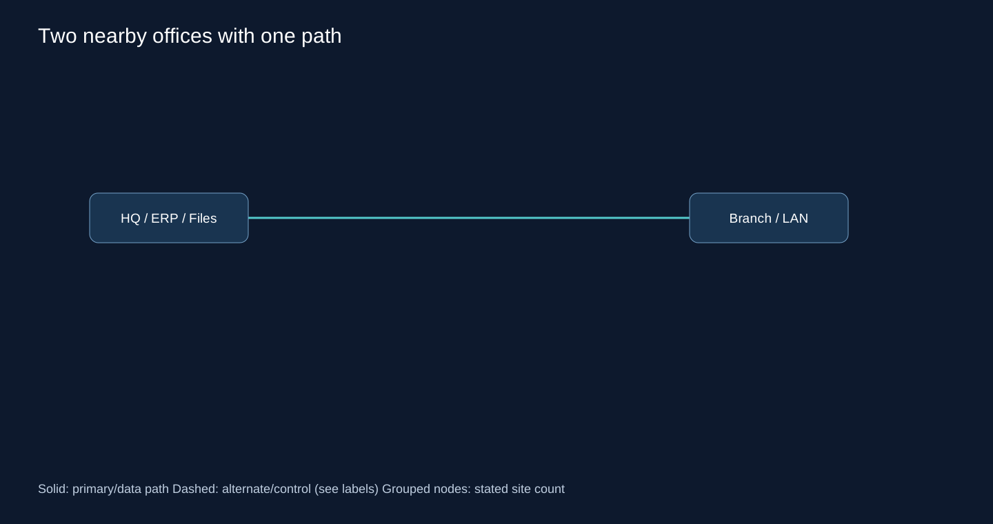
Two MikroTik routers, one ISP each, one tunnel, central ERP and File Server. Assume non-overlapping 10.10.0.0/24 and 10.20.0.0/24.
2. Network Topology
A routed point-to-point VPN; no stretched Windows broadcast domain.
3. Routing Options
Static routes in both directions; OSPF if subnet changes are frequent. BGP adds policy machinery with no current requirement.
4. Recommended Architecture
I would use explicit corporate static routes and keep local Internet defaults.
5. Why This Design?
There is one usable path. A dynamic protocol cannot provide physical redundancy; the two routes are easy to audit.
6. Tunnel / WAN Transport
WireGuard for a supported MikroTik pair; IPsec when peer interoperability, required crypto policy or organizational standards favor it. Measure SMB latency before moving file workflows.
7. Failure Scenario
ISP/tunnel loss disconnects remote ERP. Router loss does too. Tracking makes the route inactive but cannot restore service without another path.
8. Security Considerations
Permit branch-to-ERP/file service flows only; management from an admin subnet. No WAN Winbox exposure.
9. Scalability
Keep a per-site address plan. Add dynamic routing when alternate paths or route churn justify it, not at an arbitrary third branch.
10. Operational Complexity
Low: backup config, handshake/traffic monitoring, route and return-path test.
Scenario 2: HQ and two strict spokes
1. Network Requirements
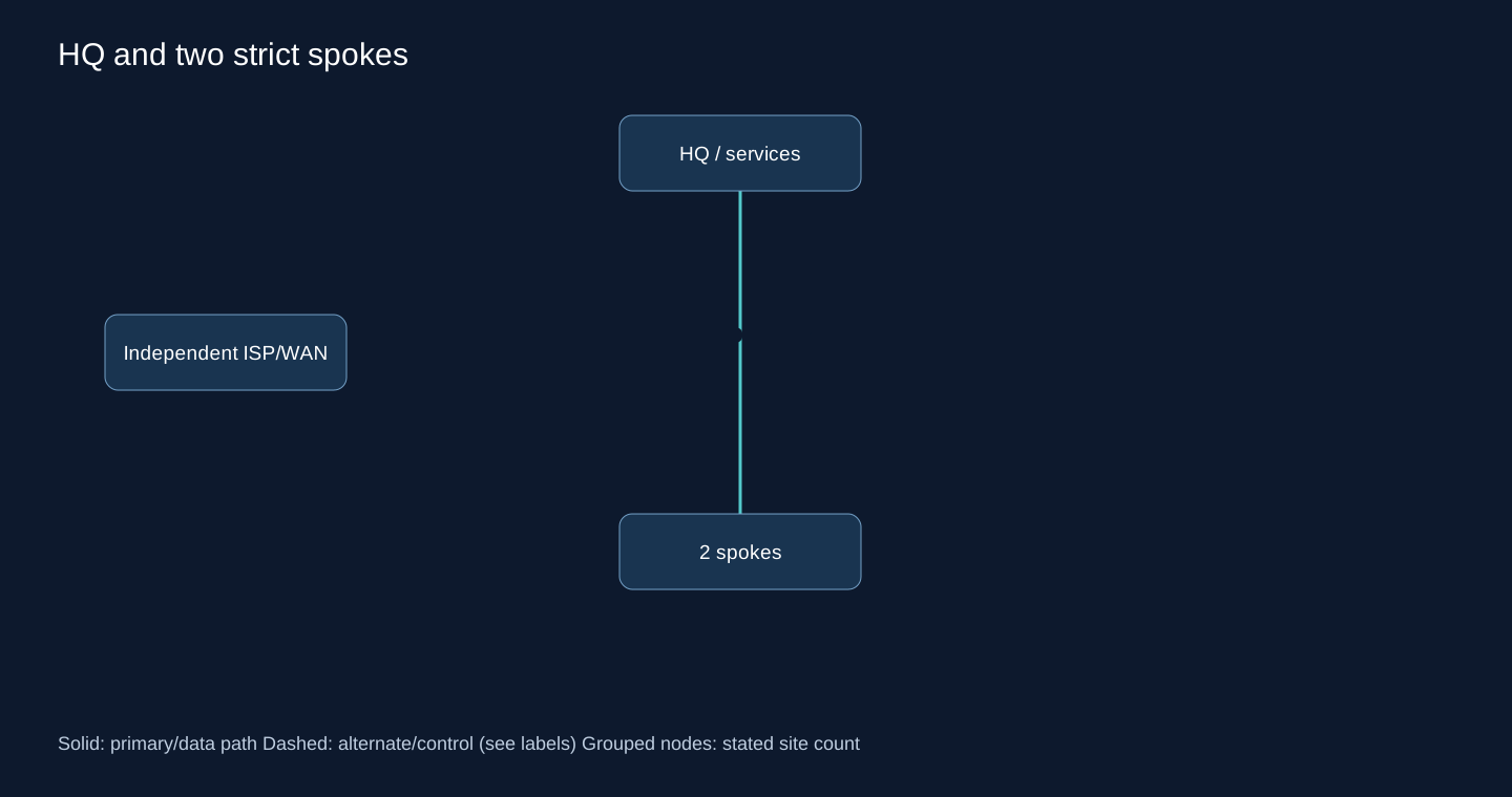
HQ hosts all corporate services; branches never initiate lateral branch traffic. Local Internet breakout is allowed.
2. Network Topology
Two tunnels terminate at HQ; the diagram groups the three organizational sites.
3. Routing Options
Specific static corporate routes; corporate default through HQ if Internet is centralized; OSPF for growing subnet inventories.
4. Recommended Architecture
Hub-and-Spoke with one assigned block per spoke, branch corporate summaries to HQ and HQ return routes.
5. Why This Design?
A full mesh creates an unneeded trust and configuration surface. A default to HQ is simplest only if all off-site traffic belongs there.
6. Tunnel / WAN Transport
Outbound WireGuard or negotiated IPsec to a reachable HQ.
7. Failure Scenario
One branch ISP failure affects that branch; HQ router failure affects both spokes. Accept or fund that single point of failure.
8. Security Considerations
Block spoke-to-spoke forwarding at HQ even if routes make it technically possible.
9. Scalability
Static remains manageable with stable summaries; two hubs change the operating problem more than two extra spokes.
10. Operational Complexity
A small inventory should map tunnel public keys, subnets and owner.
Scenario 3: Five Tehran branches: VoIP, ERP and CCTV
1. Network Requirements
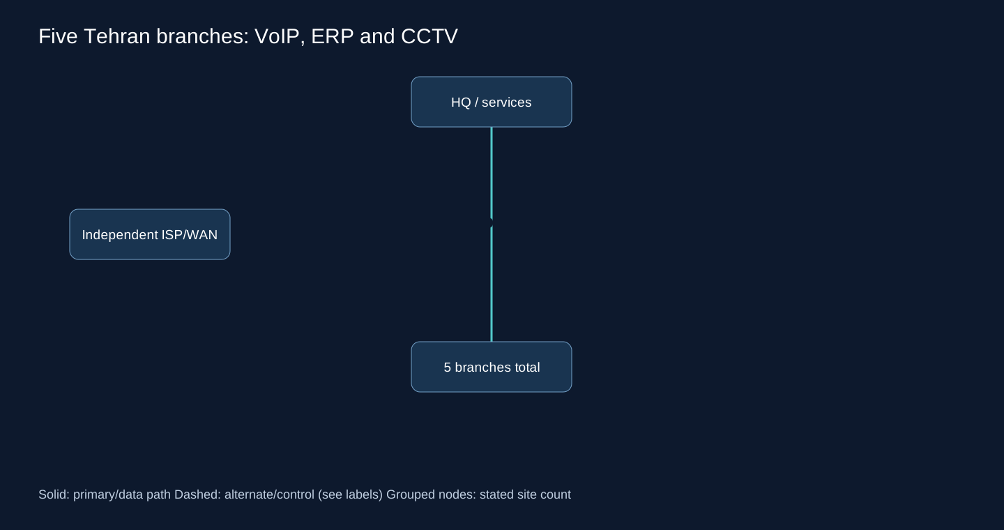
MikroTik branches, Windows users and central services. CCTV recording is assumed local; only authorized viewing crosses WAN.
2. Network Topology
Five spokes to HQ, each with distinct user, voice and camera subnets.
3. Routing Options
Static summaries; OSPF with passive LANs; BGP with per-spoke filters.
4. Recommended Architecture
Use static site blocks for a stable single-path network; select OSPF if VLAN additions are frequent and operationally approved.
5. Why This Design?
Five is not an OSPF threshold. BGP policy is valuable only if the organization needs separate import/export decisions. QoS and capacity, not protocol choice, protect voice from camera traffic.
6. Tunnel / WAN Transport
Encrypted routed VPN; reserve capacity using measured codec streams, not an assumed Mbps per branch.
7. Failure Scenario
An HQ outage removes central call/ERP reachability; local camera recording must continue. No routing protocol fixes application centralization.
8. Security Considerations
Camera VRF/VLAN isolation, voice ACLs, no camera default access to users.
9. Scalability
Summaries survive more VLANs inside allocated blocks. Reconsider routing at the first dual-path requirement.
10. Operational Complexity
Static has fewer sessions; OSPF removes some route edits but adds neighbor/LSDB monitoring. BGP adds policy review.
Scenario 4: Five branches with two WAN paths
1. Network Requirements
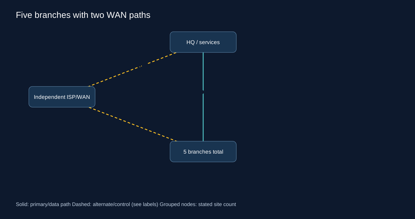
Two ISPs and two tunnels per branch; HQ reachable through diverse uplinks. Primary/backup, not session load sharing, is required.
2. Network Topology
Two parallel branch-HQ paths; pin each outer endpoint route to its intended ISP.
3. Routing Options
Floating statics with tracking; recursive probe routes; OSPF unequal costs; BGP preference; equal-cost ECMP only for deliberate active/active.
4. Recommended Architecture
For five stable sites I would start with tracked primary and floating backup, with independent remote probes and a restoration delay.
5. Why This Design?
Plain floating routes do not notice a failed upstream while the modem responds. Recursive resolution only works if scope/target-scope and probe pinning are correct. OSPF/BGP become worthwhile as path policy grows.
6. Tunnel / WAN Transport
One encrypted tunnel per underlay; avoid both endpoints resolving through the same default after failure.
7. Failure Scenario
Tracking withdraws primary after probe failure; OSPF waits for link/neighbor detection then SPF; BGP withdraws on session/BFD failure then selects backup. ECMP removes the dead member only after detection. Existing stateful sessions may reset.
8. Security Considerations
Apply identical authorized prefix/service filters on both tunnels; test return traffic through the same firewall state domain.
9. Scalability
At dozens of policy variants, replace bespoke tracking scripts with templates or dynamic routing.
10. Operational Complexity
Moderate: monitor probe path, tunnel traffic and failback; do not only ping the ISP gateway.
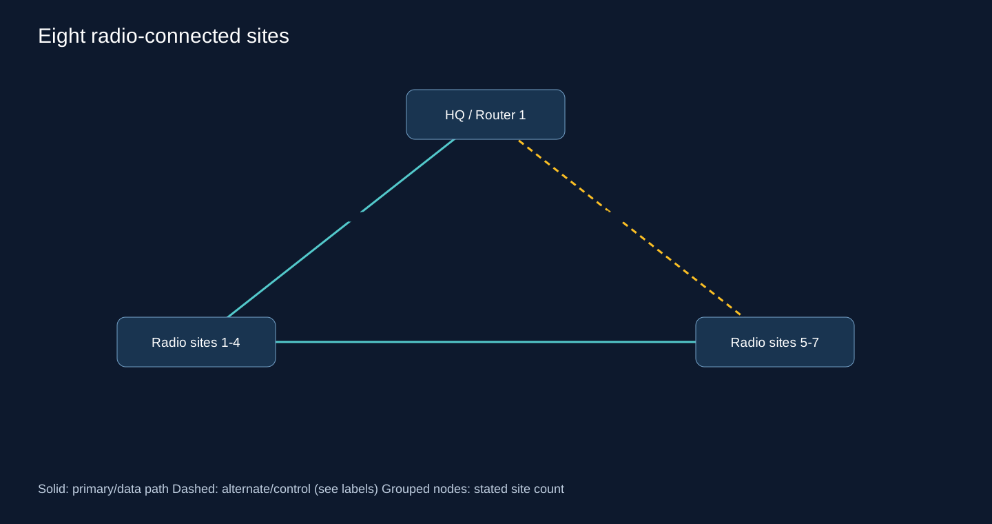
Scenario 5: Eight radio-connected sites
1. Network Requirements
Fixed point-to-point radios with varying loss/latency; some paths form a ring. This is not a mobile mesh.
2. Network Topology
Routed links with alternate radio hops, no large bridged camera domain.
3. Routing Options
OSPF; EIGRP on an all-compatible Cisco estate; static for strictly leaf sites; BGP for policy boundaries.
4. Recommended Architecture
Use OSPF point-to-point adjacencies and costs based on usable capacity and intended primary paths. Keep stable static leaves if they have no alternate.
5. Why This Design?
OSPF makes alternate topology visible. EIGRP is valid when already supported, but not across MikroTik. BGP does not automatically measure radio quality; introducing AS policy here may not solve the actual problem.
6. Tunnel / WAN Transport
Radio Ethernet handoff; add encryption if radio security and physical trust do not meet policy.
7. Failure Scenario
Link flapping triggers repeated SPF. Repair RF/interference first; use measured timer/debounce choices. Very fast BFD on lossy links can increase outages.
8. Security Considerations
Separate radio management; authenticate routing; prevent untrusted LAN neighbors.
9. Scalability
Bound the radio domain and summarize at a regional boundary if new rings grow.
10. Operational Complexity
Track RF signal, retransmissions, jitter and route events together. A protocol-only dashboard misses the cause.
Scenario 6: Ten mixed Cisco and MikroTik branches
1. Network Requirements
Two vendor families, shared operations and a few alternate paths. No EIGRP implementation on native RouterOS.
2. Network Topology
HQ hub with routed branch links; LAN routing remains local.
3. Routing Options
OSPF interoperability; static summaries; eBGP with explicit peer policies.
4. Recommended Architecture
Choose OSPF when a shared IGP is wanted; passive LAN interfaces and explicit router IDs. Keep vendor-specific syntax in separate templates.
5. Why This Design?
Standard packet formats allow adjacency, but timer, MTU, authentication and network-type defaults still require matching. EIGRP is not a multi-vendor plan here.
6. Tunnel / WAN Transport
A mutually supported IPsec/GRE design; WireGuard only on endpoints actually implementing it. Do not assume Cisco IOS XE has the same WireGuard feature set.
7. Failure Scenario
Failover follows OSPF detection and SPF; test each vendor as the failed endpoint and validate next-hop installation.
8. Security Considerations
Permit protocol 89 on transit only; restrict redistribution of connected WAN/management networks.
9. Scalability
Adopt BGP at a regional/provider boundary when import/export policy becomes necessary.
10. Operational Complexity
Ansible inventory per OS; common intent and separate rendered configs; compare neighbors and prefix counts after changes.
Scenario 7: Twelve branches behind CGNAT
1. Network Requirements
Some branches have no inbound public address; all require central services. HQ has a reachable stable VPN endpoint.
2. Network Topology
Spokes initiate connections to a public hub. CGNAT prevents unsolicited direct inbound sessions unless the provider supplies a mapping/service.
3. Routing Options
Static corporate routes; BGP over established tunnels; OSPF only with a supported multicast/unicast neighbor design.
4. Recommended Architecture
Outbound WireGuard with keepalive where needed and static summaries initially; BGP for frequent prefix or path changes.
5. Why This Design?
BGP initiation also comes from the spoke when needed. Dynamic routing cannot create a public endpoint through arbitrary CGNAT or defeat blocked UDP.
6. Tunnel / WAN Transport
WireGuard UDP or IPsec NAT-T if supported by provider NAT behavior. Validate timeout and address changes; do not promise direct spoke mesh.
7. Failure Scenario
A changed NAT mapping requires re-establishment/keepalive. Hub loss disconnects every dependent spoke unless a second public hub exists.
8. Security Considerations
Authenticate peer keys independently of observed public source; restrict tunnel source prefixes and service forwarding.
9. Scalability
Add a second outbound tunnel per branch to a diverse hub before adding direct branch links.
10. Operational Complexity
Monitor age of last handshake plus real probe traffic; an idle handshake alone is not an outage metric.
Scenario 8: Fifteen cities and central-only services
1. Network Requirements
One ISP per branch; service prefixes are stable; HQ outage tolerance must be agreed.
2. Network Topology
Single hub now; a second hub only helps if it has diverse access and reachable services.
3. Routing Options
Static site summaries; OSPF for common topology; BGP for strict per-site policy.
4. Recommended Architecture
Keep templated static routing if changes are rare; prioritize a tested dual-hub service plan over switching protocol for the number 15.
5. Why This Design?
Fifteen branches alone does not require dynamic routing. A second router at the same HQ and ISP is not an independent disaster-recovery design.
6. Tunnel / WAN Transport
Encrypted hub-spoke VPN over each Internet link.
7. Failure Scenario
A branch ISP loss remains a branch outage; dual hub protects hub loss, not the only last-mile circuit.
8. Security Considerations
Do not distribute all branch routes if only central services are allowed; firewall lateral traffic explicitly.
9. Scalability
A common address allocation keeps static templates viable; dual-path service policy may trigger BGP migration.
10. Operational Complexity
Audit route drift and scheduled backup restore; compare maintenance effort to dynamic neighbor management.
Scenario 9: Twenty branches and two data centers
1. Network Requirements
DC1 and DR both host active but distinct services. Replication and application readiness are separate from routing.
2. Network Topology
Each branch reaches both DCs; a diverse inter-DC core carries permitted transit.
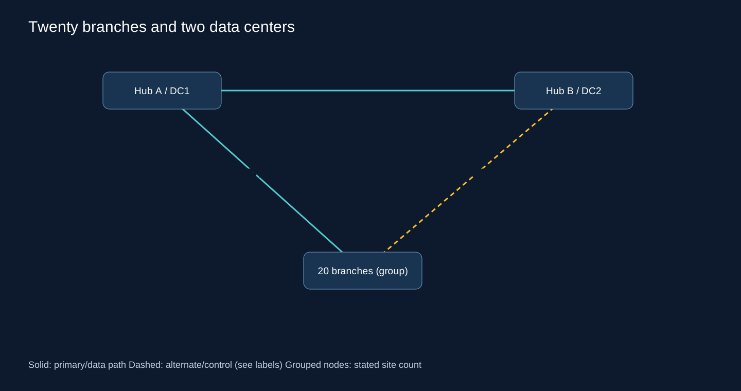
3. Routing Options
One well-designed OSPF domain; BGP WAN; hybrid with OSPF inside each DC.
4. Recommended Architecture
Use eBGP at WAN edges and local IGP per DC where independent service policy is needed. Announce each service prefix from sites that can actually serve it.
5. Why This Design?
A summary saying DC is reachable cannot prove every application is ready at DR. Hybrid contains internal churn and keeps prefix policy at the WAN boundary.
6. Tunnel / WAN Transport
Two encrypted access paths; independent inter-DC transport, not a loop through an arbitrary branch.
7. Failure Scenario
DC loss withdraws its prefixes. DR advertises moved service prefixes only after readiness checks. Coordinate outgoing and return preference to avoid stateful firewall asymmetry.
8. Security Considerations
Service VRFs and explicit inter-DC filters; route leak approval belongs with firewall change review.
9. Scalability
Allocate regional/site blocks, but do not aggregate prefixes whose DR behavior differs.
10. Operational Complexity
Moderate/high: test service moves, routing withdrawal and firewall state together.
Scenario 10: Twenty industrial IT/OT sites
1. Network Requirements
Factories, warehouses and HQ over fiber, radio and private WAN. OT maintenance windows are limited; some controllers cannot route dynamically.
2. Network Topology
Routed regional access with separate OT/IT VRFs and a firewall-controlled shared-services boundary.
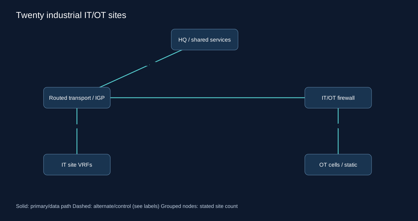
3. Routing Options
Static OT leaf routes; OSPF transport; BGP between regions when policy requires.
4. Recommended Architecture
Use OSPF only on managed infrastructure links and static/default at isolated OT cells. Leak minimum historian/DNS/NTP services through reviewed firewalls.
5. Why This Design?
Convergence speed must not override deterministic security boundaries. A PLC should not become an IGP neighbor or learn the entire enterprise.
6. Tunnel / WAN Transport
Fiber/radio/private service; encrypt untrusted segments according to safety and latency requirements.
7. Failure Scenario
A radio cut reroutes infrastructure traffic where alternate capacity exists; a cell firewall failure follows the approved HA/safety behavior, not a routing bypass.
8. Security Considerations
Deny IT-to-OT by default, allow explicit industrial flows; out-of-band management and protected configuration backups.
9. Scalability
Add cells as bounded prefixes/VRFs; preserve regional failure domains.
10. Operational Complexity
Change control and approved maintenance windows dominate cost; automation must honor them.
Scenario 11: Thirty dual-ISP branches
1. Network Requirements
Dual-WAN per branch, central services and measured failover target. Stateful firewalls favor primary/backup initially.
2. Network Topology
Each underlay has a pinned VPN path to a hub; physical ISP diversity must be verified.
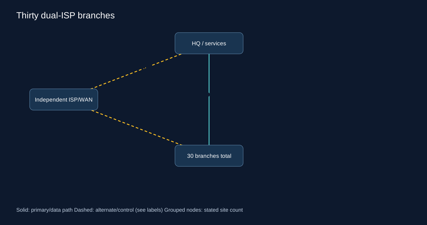
3. Routing Options
OSPF over GRE/IPsec; BGP over WireGuard on supported endpoints; static tracking. ECMP for approved independent flows.
4. Recommended Architecture
Choose filtered eBGP with primary/backup preference when per-site policies differ. OSPF is a simpler alternative if all paths share one policy.
5. Why This Design?
Static tracking at 60+ tunnels can work with automation but creates many probe dependencies. Active/active increases capacity use but also asymmetry and troubleshooting work.
6. Tunnel / WAN Transport
WireGuard for RouterOS peers or interoperable GRE/IPsec. Never let the outer tunnel endpoint route depend on its own inner BGP route.
7. Failure Scenario
BFD only after packet-loss testing and mutual mode support; otherwise tune hold/dead detection to the service objective. Backup ISP loss should alarm while primary stays active.
8. Security Considerations
Per-branch exact prefix filters, control-plane ACL and no unintended Internet transit.
9. Scalability
Templates and a second independent hub are the next useful investments.
10. Operational Complexity
Monitor selected route plus both candidate paths; session up alone cannot show which ISP carries ERP.
Scenario 12: Fifty nationwide mixed-WAN branches
1. Network Requirements
Central DC, mixed single/dual Internet and private WAN, moderate route changes. Assume the team can maintain filters and automated templates.
2. Network Topology
Access through redundant regional or central hubs; retain local routed LAN domains.
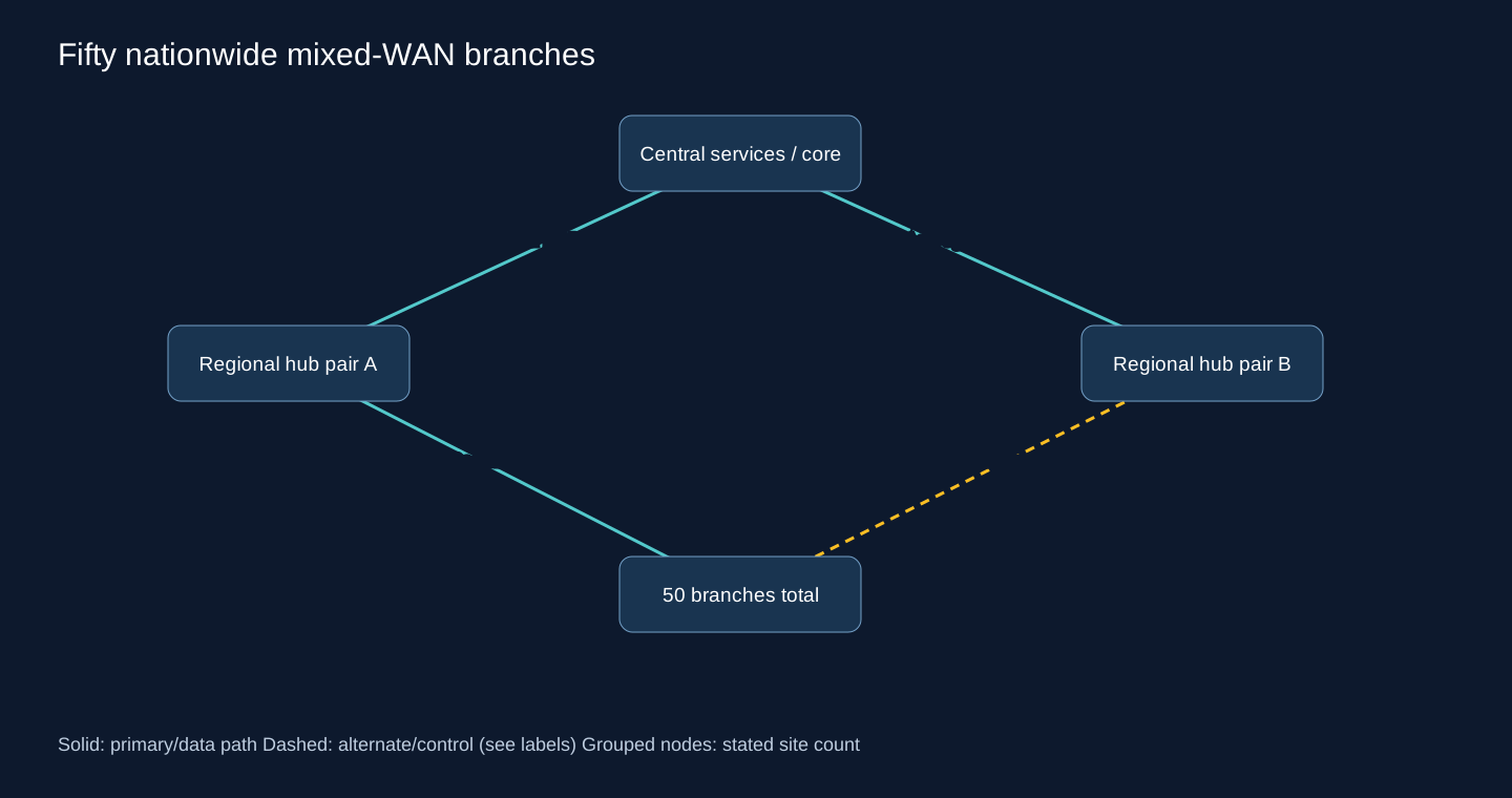
3. Routing Options
Single-area OSPF can work if churn/LSDB/CPU are bounded. Multi-area helps only with real boundaries. BGP/hybrid gives policy. Static/default remains possible for fixed leaf routes. MPLS L3VPN and SD-WAN are service/architecture choices.
4. Recommended Architecture
Under these assumptions I choose BGP at WAN boundaries, OSPF inside larger sites and explicit static leaves for simple branches. Regional hubs are justified by latency/capacity, not the number 50.
5. Why This Design?
A single IGP over heterogeneous failure behavior can spread churn. Creating 50 areas without aggregation or stable backbone adds work. SD-WAN is justified by application-aware SLA steering and lifecycle operations, not as a new name for BGP.
6. Tunnel / WAN Transport
Use private WAN where SLA warrants cost and encrypted Internet backup. Keep CE-PE policy separate from VPN overlay.
7. Failure Scenario
A regional hub loss moves affected spokes to the other hub; a provider outage withdraws only that transport route. Confirm backup bandwidth can carry critical traffic.
8. Security Considerations
Corporate, guest, camera and management segmentation; allow only assigned branch aggregates on ingress.
9. Scalability
Add regional domains and preallocated summaries; avoid arbitrary redistribution between every region.
10. Operational Complexity
NetBox inventory, config generation, staged deployment, latency/loss and route-change alerting become routine work.
Scenario 13: Eighty MPLS branches with Internet backup
1. Network Requirements
Provider L3VPN primary, Internet VPN backup; contract includes per-VRF routing and supported CE-PE options.
2. Network Topology
CE to PE on private WAN; separate encrypted branch-to-hub Internet overlay.
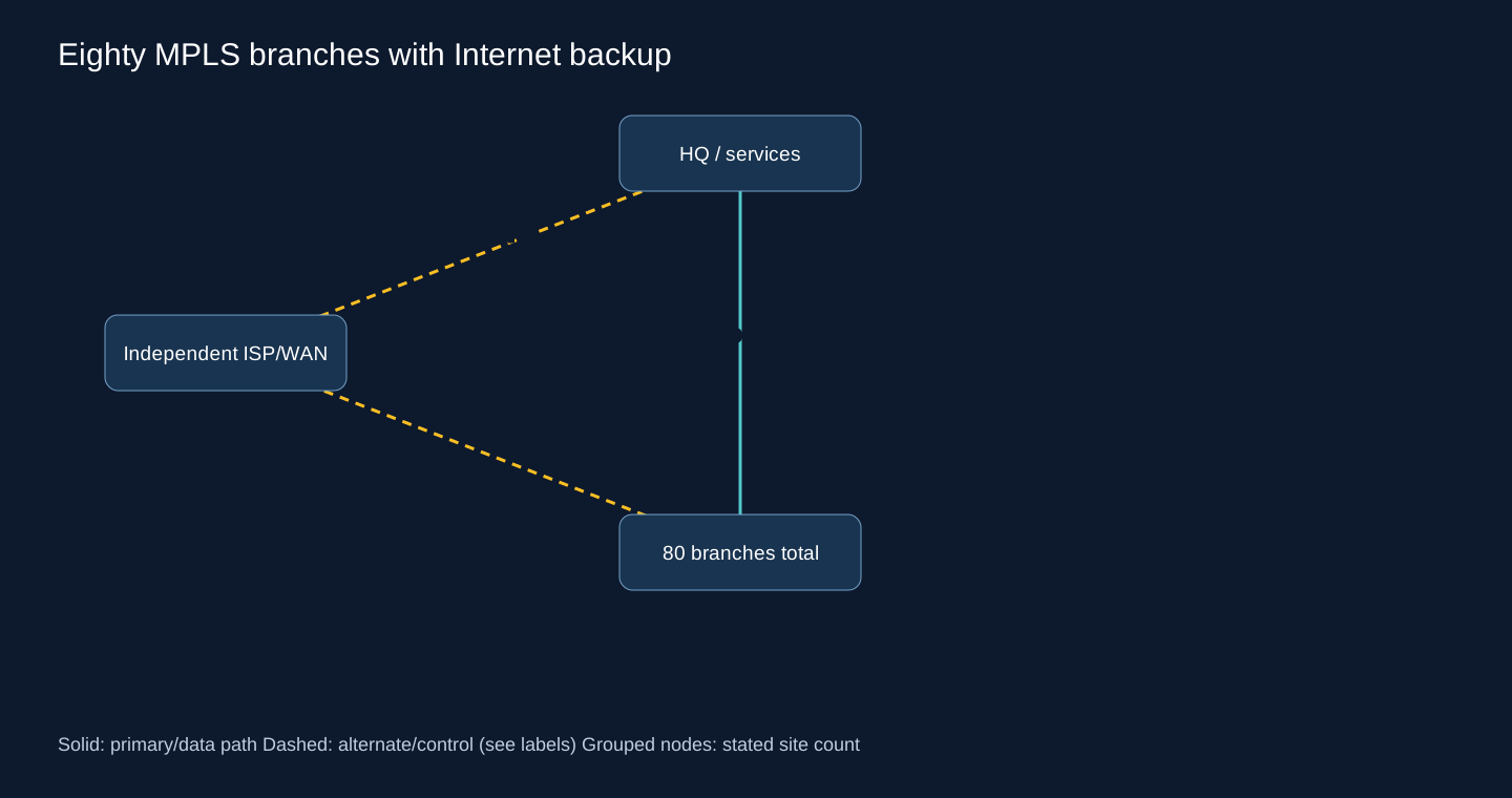
3. Routing Options
CE-PE static; OSPF if provider offers it; eBGP for explicit exchange and preference.
4. Recommended Architecture
Prefer CE-PE eBGP with strict filters, and a less-preferred BGP VPN path. Match route preference across domains on the actual platform.
5. Why This Design?
Customer CE-PE routing is independent of provider IGP, labels and MP-BGP VPN distribution. You do not configure the provider core by enabling OSPF on the CE.
6. Tunnel / WAN Transport
MPLS L3VPN and IPsec/WireGuard backup according to endpoint support. MPLS is not encryption.
7. Failure Scenario
PE link up can coexist with a remote provider black hole. Use end-to-end service-prefix probes and agreed provider withdrawal/conditional routing. Prevent backup prefixes leaking back as primary.
8. Security Considerations
Filter route targets/service imports at provider boundary by contract; CE still enforces authorized prefixes and traffic.
9. Scalability
Use allocated site aggregates and prefix budgets per attachment. Renumber or NAT only at deliberate overlap boundaries.
10. Operational Complexity
Provider ticket visibility, route counts, SLA evidence and backup drills; monitor ISP2 even while MPLS is healthy.
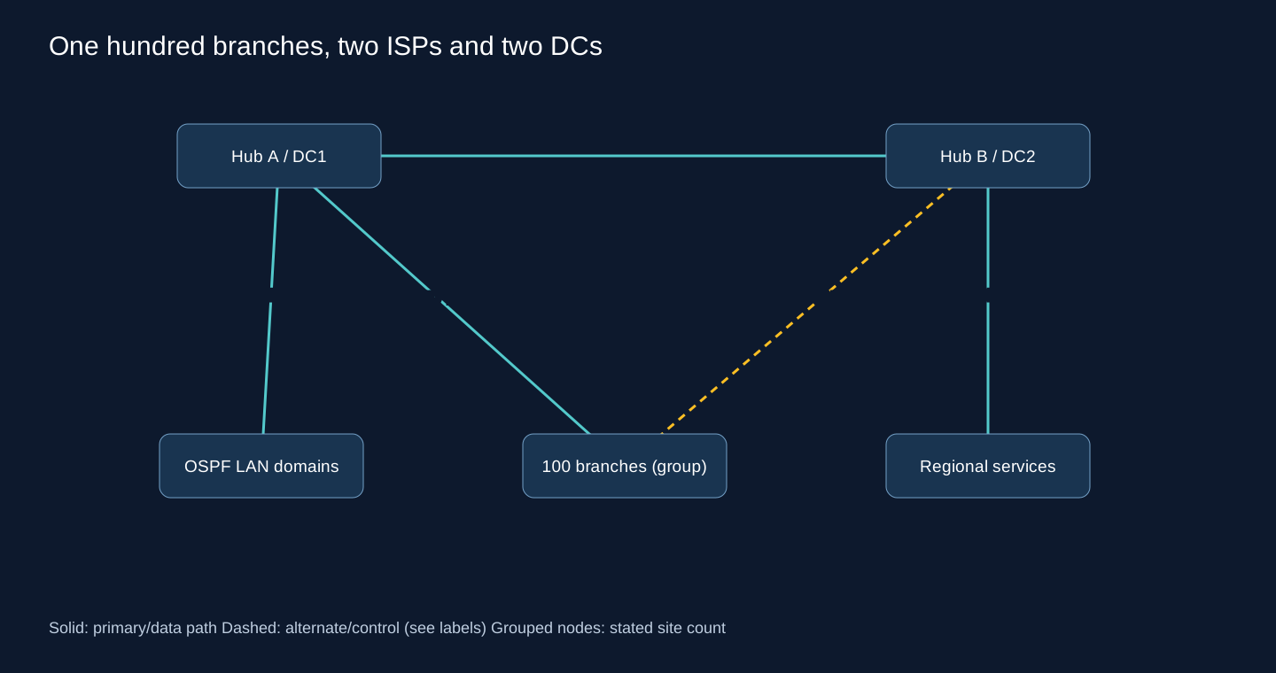
Scenario 14: One hundred branches, two ISPs and two DCs
1. Network Requirements
Central and regional ERP/voice services, dual WAN, redundant hubs, monitoring and an operating team with change control.
2. Network Topology
BGP WAN between branch/regional/DC edges; separate OSPF LAN domains.
3. Routing Options
eBGP branch ASNs; iBGP WAN with redundant RRs where required; SD-WAN if SLA-aware orchestration is a requirement.
4. Recommended Architecture
Hybrid BGP WAN + OSPF local with dual hubs and service-specific communities/preferences. Use RRs only for an actual iBGP distribution requirement.
5. Why This Design?
Per-region policy avoids sending all voice/ERP through one DC unnecessarily. One hundred branches does not itself create an iBGP full-mesh problem if access uses eBGP.
6. Tunnel / WAN Transport
Diverse encrypted Internet and private WAN; pin endpoints and budget encryption throughput at each hub.
7. Failure Scenario
Lose an ISP, hub or DC separately; each should affect only intended prefixes. Regional service outages need application-aware withdrawal, not blanket hub shutdown.
8. Security Considerations
VRFs by trust boundary, default-deny route export and management isolation. Public routing policy separate from private WAN ASNs.
9. Scalability
Consistent addressing and regional summaries support the next 100 branches without a global redistribution redesign.
10. Operational Complexity
Automate approved prefix lists and diff review; monitor route changes, not only session counts.
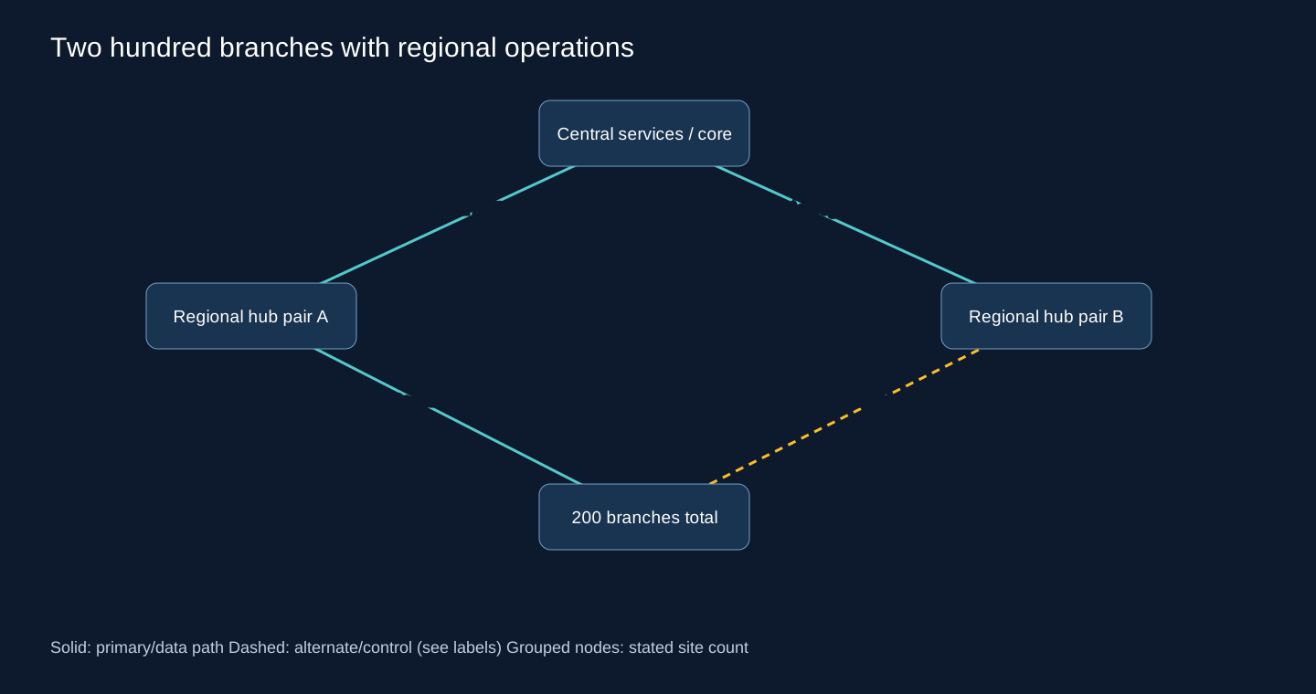
Scenario 15: Two hundred branches with regional operations
1. Network Requirements
Critical services, centralized management, automated provisioning, HA, segmentation and multiple regions.
2. Network Topology
Redundant regional hub pairs connect to a resilient core; branch routes aggregate where failure semantics permit.
3. Routing Options
Hierarchical BGP WAN; OSPF regional/local domains; managed MPLS; SD-WAN orchestration.
4. Recommended Architecture
BGP regional boundaries with distinct local IGPs. Select SD-WAN if centralized policy, zero-touch provisioning and measured path steering justify platform cost and dependency.
5. Why This Design?
Regional isolation reduces the blast radius of a bad prefix or flapping tunnel. MPLS can provide service guarantees but does not replace configuration lifecycle management.
6. Tunnel / WAN Transport
Mix contracted private WAN with independent Internet VPN; keep critical local services available during core isolation.
7. Failure Scenario
A regional hub failure must not withdraw healthy prefixes in other regions. Test region isolation and recovery without a full-table resynchronization storm.
8. Security Considerations
Per-tenant/trust VRFs, authenticated bootstrap, controlled secrets and separate automation privileges.
9. Scalability
Capacity-plan tunnel/SA/session/FIB headroom, including one surviving hub carrying the whole region.
10. Operational Complexity
High design effort, lower repeatable provisioning effort; staged rollouts and rollback artifacts are mandatory operating controls.
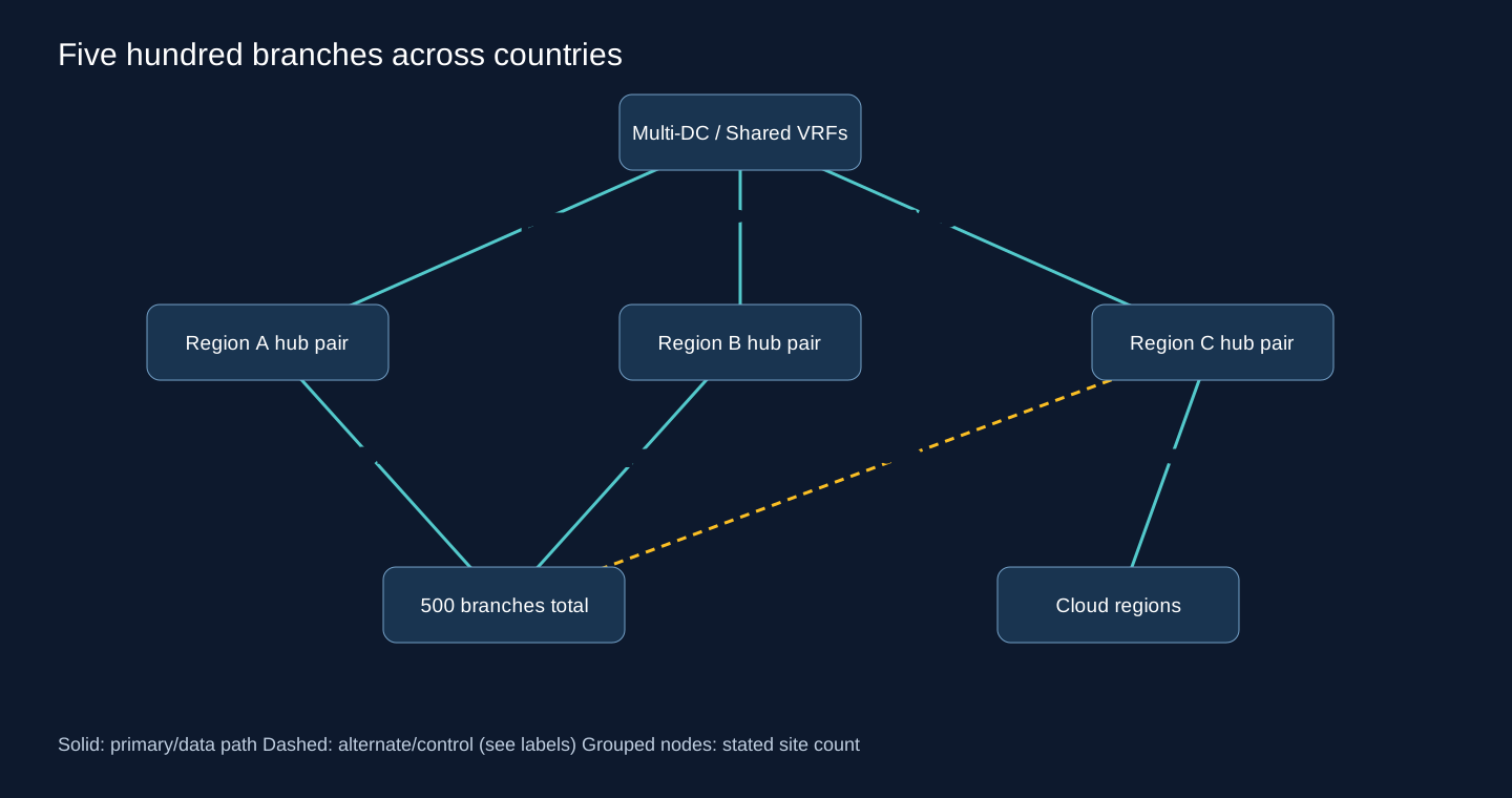
Scenario 16: Five hundred branches across countries
1. Network Requirements
Several DCs/cloud regions/ISPs, private WAN and Internet VPN, local breakout and shared services. Jurisdiction, latency and cross-border failures matter.
2. Network Topology
Regional routing domains with redundant hubs, filtered core interconnect and separate cloud edges; diagram groups 500 branches, not 500 full-mesh routers.
3. Routing Options
BGP-based WAN; hierarchical OSPF/IS-IS within supported cores; MP-BGP VPN families; SD-WAN; EVPN only for specific supported fabrics/services.
4. Recommended Architecture
Use regional BGP boundaries and VRFs, redundant RRs only in iBGP domains, localized IGPs and controlled inter-region/cloud export. Automate intent from an approved inventory.
5. Why This Design?
One enormous routing domain couples every tunnel flap, maintenance action and accidental external route to too many routers. Separate domains reduce that coupling but require explicit transit, summaries and troubleshooting ownership.
6. Tunnel / WAN Transport
Private WAN for required SLA, encrypted Internet fallback and diverse cloud connections. Local breakout follows security inspection policy, not simply shortest path.
7. Failure Scenario
Simulate country isolation, cloud-region loss and dual hub failure. DR must include identity, DNS, databases and reachable service prefixes. A healthy BGP backbone alone is not successful DR.
8. Security Considerations
Regional security boundaries, minimum shared-service route imports, no guest/OT route leak, Internet RPKI where relevant and audited automation identities.
9. Scalability
Budget prefixes and sessions per region, summarize by ownership, reserve address/ASN space and test worst-case surviving capacity.
10. Operational Complexity
Dedicated operations, telemetry retention, canary deployments, automated pre/post checks and regional rollback. Complexity is managed explicitly rather than hidden inside a giant IGP.
Decision table: the recommendation and its assumptions
| Scenario | Branches / sites | Routing | Tunnel/WAN | Topology | Reason |
|---|---|---|---|---|---|
| Two nearby offices with one path | 2 | Static | WireGuard / IPsec | Point-to-Point | One path, two explicit prefixes |
| HQ and two strict spokes | 3 | Static / corporate summary | Outbound VPN | Hub-and-Spoke | Stable reachability and no lateral traffic |
| Five Tehran branches: VoIP, ERP and CCTV | 5 | Static; OSPF when route churn grows | Encrypted VPN | Hub-and-Spoke | Stable summaries, voice capacity planning |
| Five branches with two WAN paths | 5 | Tracked static / OSPF alternative | Two VPNs / diverse ISPs | Hybrid WAN | Track the remote path, not modem status |
| Eight radio-connected sites | 8 | OSPF; compatible EIGRP optional | Point-to-Point Radio | Ring / partial mesh | Alternate topology without radio-quality assumptions |
| Ten mixed Cisco and MikroTik branches | 10 | OSPF / static edges | Mutually supported GRE/IPsec | Hub-and-Spoke | Standards plus tested defaults |
| Twelve branches behind CGNAT | 12 | Static or eBGP over tunnel | Outbound WireGuard / NAT-T | Hub-and-Spoke | NAT reachability first |
| Fifteen cities and central-only services | 15 | Templated static; dynamic conditional | Encrypted Internet VPN | Hub / optional Dual-Hub | Change rate matters more than 15 |
| Twenty branches and two data centers | 20 | BGP WAN + OSPF local | Diverse encrypted links | Dual-DC / Dual-Hub | Independent service policy and failure domains |
| Twenty industrial IT/OT sites | 20 | OSPF transport + static OT | Fiber / Radio / private WAN | Segmented regional | Keep control systems outside routing churn |
| Thirty dual-ISP branches | 30 | eBGP or common-policy OSPF | WireGuard / GRE-IPsec | Dual-WAN | Explicit preference, measured detection |
| Fifty nationwide mixed-WAN branches | 50 | BGP WAN / OSPF sites / static leaves | Private WAN + encrypted Internet | Regional / Hybrid WAN | Heterogeneous transport and bounded churn |
| Eighty MPLS branches with Internet backup | 80 | CE-PE eBGP + backup policy | MPLS L3VPN + Internet VPN | Hybrid WAN | Explicit customer-provider boundary |
| One hundred branches, two ISPs and two DCs | 100 | BGP WAN + OSPF LAN | Dual-ISP VPN / private WAN | Hybrid Dual-Hub | Service policy and contained LAN changes |
| Two hundred branches with regional operations | 200 | Regional BGP + local IGP | MPLS / VPN / optional SD-WAN | Hierarchical regional | Provisioning and bounded failure domains |
| Five hundred branches across countries | 500 | Regional BGP / MP-BGP + local IGP | Private WAN / encrypted Internet / cloud | Multi-Region hierarchical | Independent policy, security and DR boundaries |
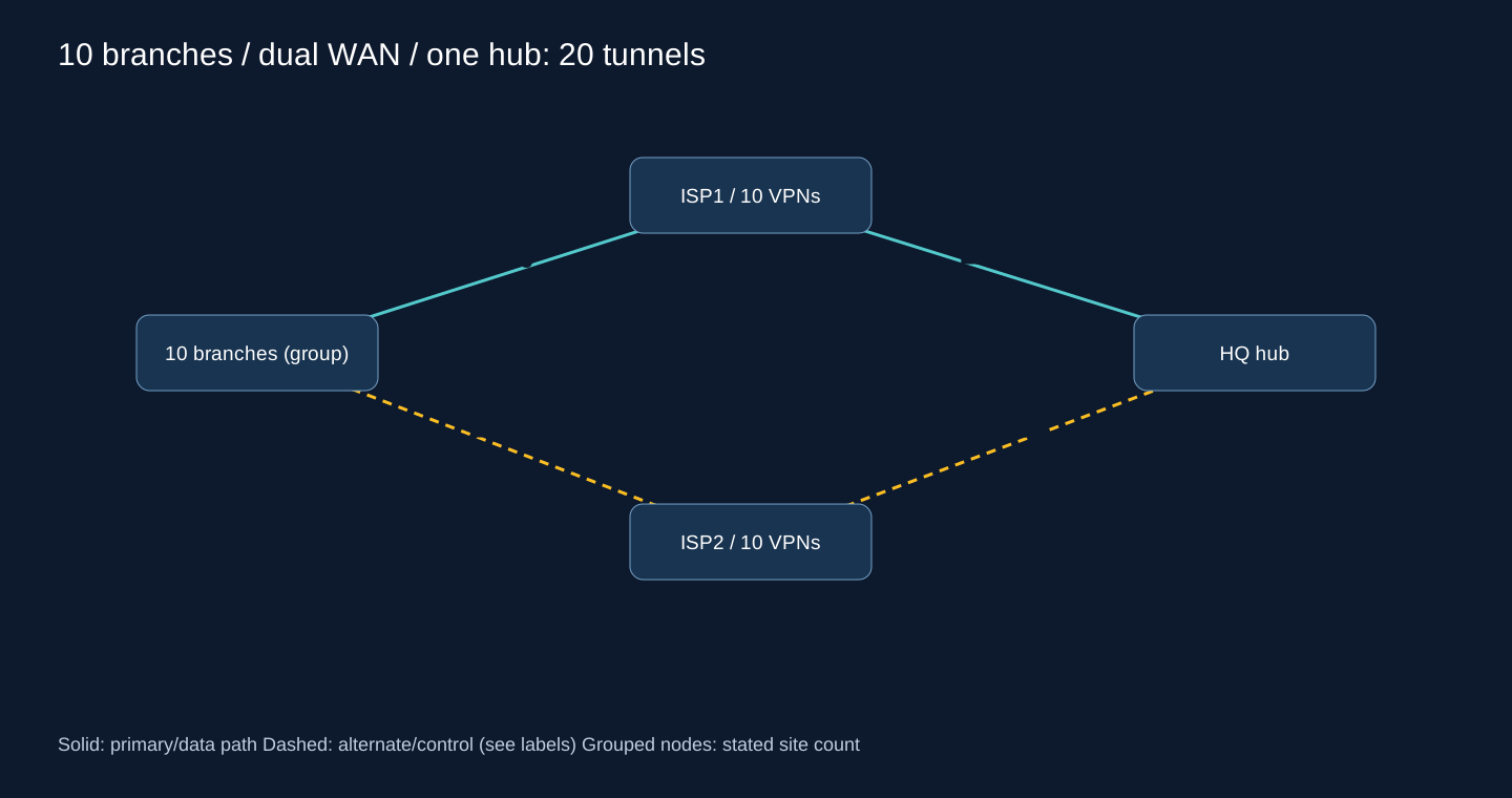
For a ten-branch dual-WAN variant, use the same topology logic as scenario 11 with ten branches: twenty access tunnels for one hub, or forty if every ISP is independently connected to both hubs. Count the actual relationships before selecting hardware.
A conditional decision tree
START
  Unique prefixes, supported endpoints, reachable WAN? -- no --> fix prerequisites
  One path + stable prefixes + acceptable outage? -- yes --> static/default + monitoring
  Alternate paths or frequent route changes? -- yes --> evaluate dynamic routing
    Shared topology and common policy? --> OSPF; EIGRP only on compatible estate
    Independent import/export or multiple providers? --> filtered BGP boundary
    Supported provider-style core and trained team? --> evaluate IS-IS vs OSPF
  Multiple DCs/regions/trust domains? --> local IGP + explicit BGP/VRF boundaries
  iBGP route distribution at scale? --> redundant RRs or justified confederation
  Application SLA steering + centralized lifecycle needed? --> evaluate SD-WAN
  Ethernet/IP VPN fabric service needed? --> evaluate supported EVPN data plane
  Low-power IoT or changing mesh? --> evaluate RPL/Babel/OLSR in their own domains
  ALWAYS --> test failure detection, return paths, security and operating cost
Read the tree as a sequence of requirements, not a branch-count ladder. In a mixed vendor network, discard unsupported options before comparing metrics. Across two DCs, define service ownership and return-path policy before picking OSPF areas or BGP attributes. SD-WAN earns its place when its telemetry, orchestration and SLA steering solve an operating requirement that plain routing plus automation does not economically meet.
Lab contract: reproducible designs, unmeasured convergence
Use separate blank CHR VMs with RouterOS 7.26 for each lab, console access and at least the stated Ethernet interfaces. No factory bridge, DHCP client/server, NAT, firewall or FastTrack rules are assumed. Do not paste these into a production router. Take VM snapshots before configuration. IPv4-only isolated links use RFC 2544 benchmark space 198.18.0.0/15; none is an Internet address. Each LAN has a test host .10/24 with gateway .1. Console administration remains available after the lab input drop. IPv6 is not configured by these labs; keep the virtual switches isolated rather than claiming IPv6 hardening.
Commands follow the current documented BGP instance/connection model, including output.filter-chain and input.filter. Earlier v7 releases may use different property names and lack this model. Replace every REPLACE_* value before execution: exchange the generated public keys between named endpoints; use a fresh matching PSK for the IPsec lab. These substitutions are required inputs, not published credentials. Expected outputs below are acceptance criteria; no RouterOS VM, Cisco image, packet capture or failover stopwatch was available during authoring.
Lab 1 — static routes over WireGuard
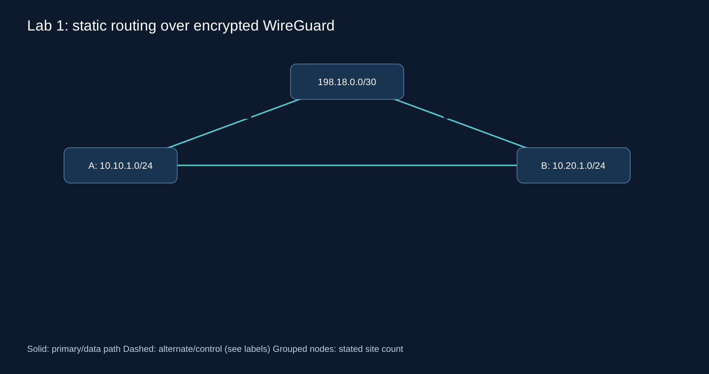
| Router | ether1 underlay | ether2 LAN | LAB-WG |
|---|---|---|---|
| A | 198.18.0.1/30 | 10.10.1.1/24 | 172.20.1.1/30 |
| B | 198.18.0.2/30 | 10.20.1.1/24 | 172.20.1.2/30 |
Connect ether1 to the same isolated virtual switch. First run the creation block on each router, copy only its public-key value to the other router, then run the peer/route block and firewall. No default route or NAT is needed because endpoints are directly connected.
A creation
/ip address add address=198.18.0.1/30 interface=ether1
/ip address add address=10.10.1.1/24 interface=ether2
/interface wireguard add name=LAB-WG listen-port=51820 mtu=1420
/ip address add address=172.20.1.1/30 interface=LAB-WG
/interface wireguard print detail where name=LAB-WG
A peer, route and firewall
/interface wireguard peers add interface=LAB-WG public-key="REPLACE_B_PUBLIC_KEY" endpoint-address=198.18.0.2 endpoint-port=51820 allowed-address=172.20.1.2/32,10.20.1.0/24 persistent-keepalive=25s
/ip route add dst-address=10.20.1.0/24 gateway=172.20.1.2 comment=LAB-STATIC
/ip firewall address-list add list=LAB-CORP address=10.10.1.0/24
/ip firewall address-list add list=LAB-CORP address=10.20.1.0/24

/ip firewall filter add chain=input action=accept connection-state=established,related comment=LAB-established
/ip firewall filter add chain=input action=drop connection-state=invalid comment=LAB-invalid
/ip firewall filter add chain=input action=accept protocol=icmp src-address-list=LAB-CORP comment=LAB-icmp
/ip firewall filter add chain=input action=accept in-interface=ether1 protocol=udp dst-port=51820 src-address=198.18.0.2 comment=LAB-WG-input
/ip firewall filter add chain=input action=accept in-interface=LAB-WG protocol=icmp comment=LAB-tunnel-icmp
/ip firewall filter add chain=input action=drop comment=LAB-input-default
/ip firewall filter add chain=forward action=accept connection-state=established,related comment=LAB-forward-established
/ip firewall filter add chain=forward action=drop connection-state=invalid comment=LAB-forward-invalid
/ip firewall filter add chain=forward action=accept src-address-list=LAB-CORP dst-address-list=LAB-CORP comment=LAB-corporate-only
/ip firewall filter add chain=forward action=drop comment=LAB-forward-default
B creation
/ip address add address=198.18.0.2/30 interface=ether1
/ip address add address=10.20.1.1/24 interface=ether2
/interface wireguard add name=LAB-WG listen-port=51820 mtu=1420
/ip address add address=172.20.1.2/30 interface=LAB-WG
/interface wireguard print detail where name=LAB-WG
B peer, route and firewall
/interface wireguard peers add interface=LAB-WG public-key="REPLACE_A_PUBLIC_KEY" endpoint-address=198.18.0.1 endpoint-port=51820 allowed-address=172.20.1.1/32,10.10.1.0/24 persistent-keepalive=25s
/ip route add dst-address=10.10.1.0/24 gateway=172.20.1.1 comment=LAB-STATIC
/ip firewall address-list add list=LAB-CORP address=10.10.1.0/24
/ip firewall address-list add list=LAB-CORP address=10.20.1.0/24

/ip firewall filter add chain=input action=accept connection-state=established,related comment=LAB-established
/ip firewall filter add chain=input action=drop connection-state=invalid comment=LAB-invalid
/ip firewall filter add chain=input action=accept protocol=icmp src-address-list=LAB-CORP comment=LAB-icmp
/ip firewall filter add chain=input action=accept in-interface=ether1 protocol=udp dst-port=51820 src-address=198.18.0.1 comment=LAB-WG-input
/ip firewall filter add chain=input action=accept in-interface=LAB-WG protocol=icmp comment=LAB-tunnel-icmp
/ip firewall filter add chain=input action=drop comment=LAB-input-default
/ip firewall filter add chain=forward action=accept connection-state=established,related comment=LAB-forward-established
/ip firewall filter add chain=forward action=drop connection-state=invalid comment=LAB-forward-invalid
/ip firewall filter add chain=forward action=accept src-address-list=LAB-CORP dst-address-list=LAB-CORP comment=LAB-corporate-only
/ip firewall filter add chain=forward action=drop comment=LAB-forward-default
Diagnostic commands
/interface wireguard peers print detail
/ip route print detail where dst-address=10.20.1.0/24
/ping 10.20.1.1 src-address=10.10.1.1 count=10
Expected output — not observed
On A, recent handshake after traffic, increasing rx/tx and an active static 10.20.1.0/24 via 172.20.1.2. Host A .10 can reach host B .10 if host firewalls permit ICMP; test the actual ERP port separately.
Failure test
/interface wireguard disable LAB-WG
# Observe loss; this lab has no alternate path. Restore:
/interface wireguard enable LAB-WG
Troubleshooting
No handshake: keys, UDP rule or endpoint. Handshake but no LAN traffic: allowed-address, return route, host gateway/firewall. Do not solve missing routes by masquerading all corporate traffic.
Rollback
Disable LAB-WG and LAB-STATIC routes if aborting; full removal uses the saved snapshot.
For a complete rollback, stop the test hosts and restore each VM’s pre-lab snapshot from the hypervisor console. An export is a reference, not an atomic restore. Never reset a production router to reproduce this lab.
Lab 2 — three-router OSPF failover
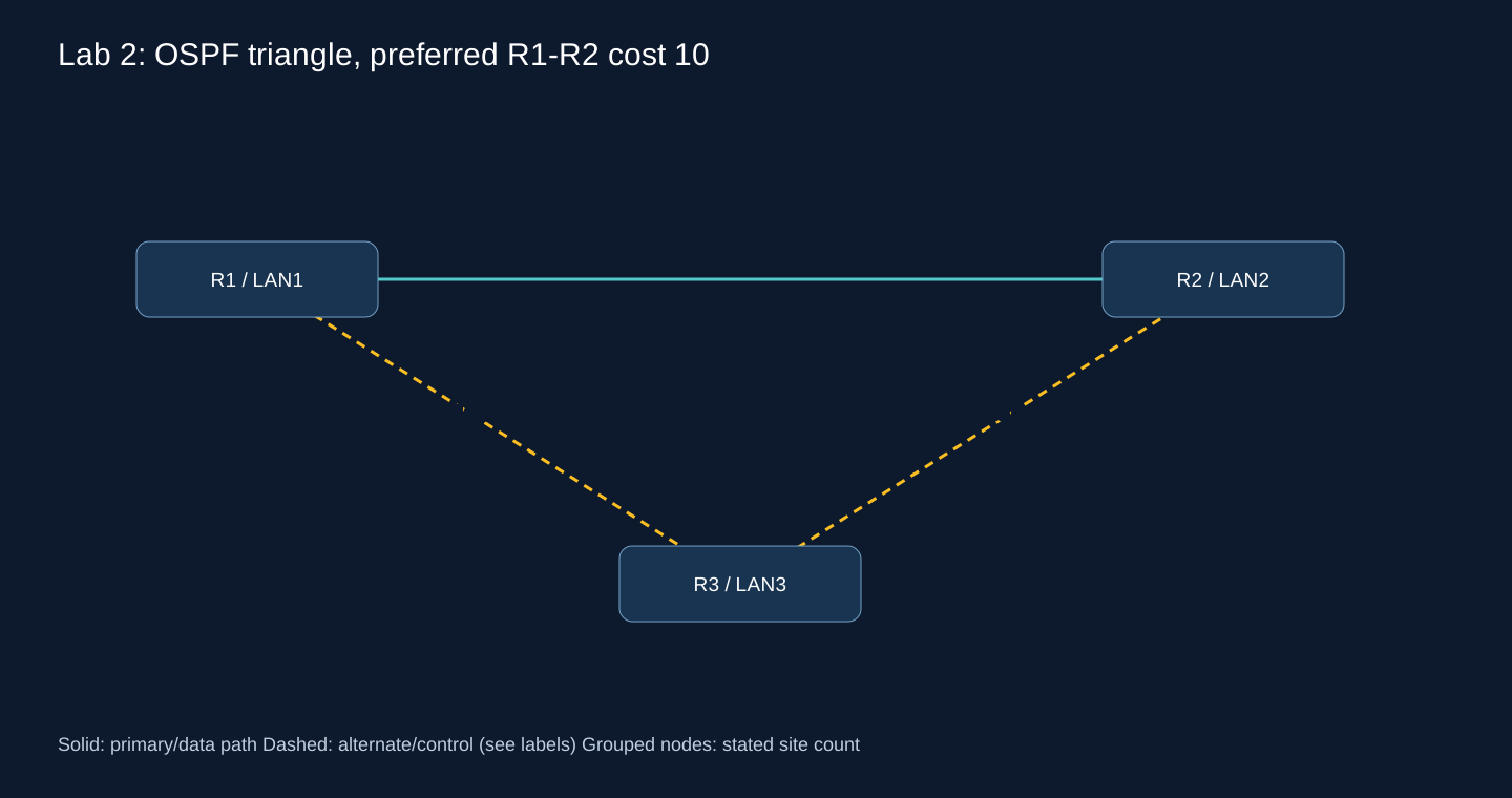
| Router | ether1 | ether2 | ether3 LAN |
|---|---|---|---|
| R1 | 10.255.12.1/30 → R2 e1 | 10.255.13.1/30 → R3 e1 | 10.1.0.1/24 |
| R2 | 10.255.12.2/30 → R1 e1 | 10.255.23.1/30 → R3 e2 | 10.2.0.1/24 |
| R3 | 10.255.13.2/30 → R1 e2 | 10.255.23.2/30 → R2 e2 | 10.3.0.1/24 |
R1
/ip address add address=10.255.12.1/30 interface=ether1
/ip address add address=10.255.13.1/30 interface=ether2
/ip address add address=10.1.0.1/24 interface=ether3
/interface list add name=LAB-TRANSIT
/interface list member add list=LAB-TRANSIT interface=ether1
/interface list member add list=LAB-TRANSIT interface=ether2
/routing ospf instance add name=LAB-OSPF version=2 router-id=10.255.0.1
/routing ospf area add name=LAB-A0 instance=LAB-OSPF area-id=0.0.0.0
/routing ospf interface-template add area=LAB-A0 interfaces=ether1 type=ptp cost=10
/routing ospf interface-template add area=LAB-A0 interfaces=ether2 type=ptp cost=20
/routing ospf interface-template add area=LAB-A0 interfaces=ether3 passive
/ip firewall address-list add list=LAB-CORP address=10.0.0.0/8

/ip firewall filter add chain=input action=accept connection-state=established,related comment=LAB-established
/ip firewall filter add chain=input action=drop connection-state=invalid comment=LAB-invalid
/ip firewall filter add chain=input action=accept protocol=icmp src-address-list=LAB-CORP comment=LAB-icmp
/ip firewall filter add chain=input action=accept protocol=ospf in-interface-list=LAB-TRANSIT src-address=10.255.0.0/16 comment=LAB-OSPF-input
/ip firewall filter add chain=input action=drop comment=LAB-input-default
/ip firewall filter add chain=forward action=accept connection-state=established,related comment=LAB-forward-established
/ip firewall filter add chain=forward action=drop connection-state=invalid comment=LAB-forward-invalid
/ip firewall filter add chain=forward action=accept src-address-list=LAB-CORP dst-address-list=LAB-CORP comment=LAB-corporate-only
/ip firewall filter add chain=forward action=drop comment=LAB-forward-default
R2
/ip address add address=10.255.12.2/30 interface=ether1
/ip address add address=10.255.23.1/30 interface=ether2
/ip address add address=10.2.0.1/24 interface=ether3
/interface list add name=LAB-TRANSIT
/interface list member add list=LAB-TRANSIT interface=ether1
/interface list member add list=LAB-TRANSIT interface=ether2
/routing ospf instance add name=LAB-OSPF version=2 router-id=10.255.0.2
/routing ospf area add name=LAB-A0 instance=LAB-OSPF area-id=0.0.0.0
/routing ospf interface-template add area=LAB-A0 interfaces=ether1 type=ptp cost=10
/routing ospf interface-template add area=LAB-A0 interfaces=ether2 type=ptp cost=20
/routing ospf interface-template add area=LAB-A0 interfaces=ether3 passive
/ip firewall address-list add list=LAB-CORP address=10.0.0.0/8

/ip firewall filter add chain=input action=accept connection-state=established,related comment=LAB-established
/ip firewall filter add chain=input action=drop connection-state=invalid comment=LAB-invalid
/ip firewall filter add chain=input action=accept protocol=icmp src-address-list=LAB-CORP comment=LAB-icmp
/ip firewall filter add chain=input action=accept protocol=ospf in-interface-list=LAB-TRANSIT src-address=10.255.0.0/16 comment=LAB-OSPF-input
/ip firewall filter add chain=input action=drop comment=LAB-input-default
/ip firewall filter add chain=forward action=accept connection-state=established,related comment=LAB-forward-established
/ip firewall filter add chain=forward action=drop connection-state=invalid comment=LAB-forward-invalid
/ip firewall filter add chain=forward action=accept src-address-list=LAB-CORP dst-address-list=LAB-CORP comment=LAB-corporate-only
/ip firewall filter add chain=forward action=drop comment=LAB-forward-default
R3
/ip address add address=10.255.13.2/30 interface=ether1
/ip address add address=10.255.23.2/30 interface=ether2
/ip address add address=10.3.0.1/24 interface=ether3
/interface list add name=LAB-TRANSIT
/interface list member add list=LAB-TRANSIT interface=ether1
/interface list member add list=LAB-TRANSIT interface=ether2
/routing ospf instance add name=LAB-OSPF version=2 router-id=10.255.0.3
/routing ospf area add name=LAB-A0 instance=LAB-OSPF area-id=0.0.0.0
/routing ospf interface-template add area=LAB-A0 interfaces=ether1 type=ptp cost=20
/routing ospf interface-template add area=LAB-A0 interfaces=ether2 type=ptp cost=20
/routing ospf interface-template add area=LAB-A0 interfaces=ether3 passive
/ip firewall address-list add list=LAB-CORP address=10.0.0.0/8

/ip firewall filter add chain=input action=accept connection-state=established,related comment=LAB-established
/ip firewall filter add chain=input action=drop connection-state=invalid comment=LAB-invalid
/ip firewall filter add chain=input action=accept protocol=icmp src-address-list=LAB-CORP comment=LAB-icmp
/ip firewall filter add chain=input action=accept protocol=ospf in-interface-list=LAB-TRANSIT src-address=10.255.0.0/16 comment=LAB-OSPF-input
/ip firewall filter add chain=input action=drop comment=LAB-input-default
/ip firewall filter add chain=forward action=accept connection-state=established,related comment=LAB-forward-established
/ip firewall filter add chain=forward action=drop connection-state=invalid comment=LAB-forward-invalid
/ip firewall filter add chain=forward action=accept src-address-list=LAB-CORP dst-address-list=LAB-CORP comment=LAB-corporate-only
/ip firewall filter add chain=forward action=drop comment=LAB-forward-default
This isolated lab deliberately omits OSPF authentication to keep first-adjacency diagnosis visible. Before an untrusted deployment configure a mutually supported cryptographic mode and matching key/id on every transit template; never enable adjacency on client LANs. Default Hello/Dead timers remain unchanged so measurements are not confused with a promised fast-failover value.
Diagnostic commands
/routing ospf neighbor print detail
/routing ospf lsa print
/ip route print detail where dst-address=10.2.0.0/24
/tool traceroute 10.2.0.1 src-address=10.1.0.1
/ping 10.2.0.1 src-address=10.1.0.1 interval=200ms count=100
Expected output — not observed
Each router has two Full point-to-point neighbors. R1 chooses R2 directly for LAN2; after the cut, next hop becomes R3 and traffic recovers. Record loss duration and FIB change; no numeric time is asserted here.
Failure test
# On R1, while a host sends continuous traffic:
/interface ethernet disable ether1
# Record route/traffic changes, then restore:
/interface ethernet enable ether1
Troubleshooting
INIT suggests one-way hellos; EXSTART suggests MTU/DD negotiation. Check network type, unique router IDs and firewall counters before changing timers.
Rollback
Re-enable ether1, disable LAB-OSPF to stop advertisements, then restore all three snapshots.
For a complete rollback, stop the test hosts and restore each VM’s pre-lab snapshot from the hypervisor console. An export is a reference, not an atomic restore. Never reset a production router to reproduce this lab.
Lab 3 — three RouterOS BGP ASNs and exact filters
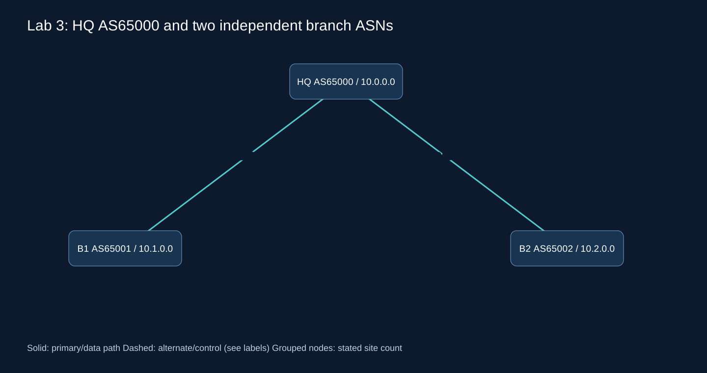
| Router | ether1 | ether2 | ether3 LAN / ASN |
|---|---|---|---|
| HQ | 10.255.1.1/30 | 10.255.2.1/30 | 10.0.0.1/24 / 65000 |
| B1 | 10.255.1.2/30 | unused | 10.1.0.1/24 / 65001 |
| B2 | 10.255.2.2/30 | unused | 10.2.0.1/24 / 65002 |
HQ
/ip address add address=10.255.1.1/30 interface=ether1
/ip address add address=10.255.2.1/30 interface=ether2
/ip address add address=10.0.0.1/24 interface=ether3
/routing bgp instance add name=LAB-BGP as=65000 router-id=10.255.0.1
/ip firewall address-list add list=LAB-ORIGIN address=10.0.0.0/24
/routing filter rule add chain=LAB-IN-B1 rule="if (dst == 10.1.0.0/24) { accept; } else { reject; }"
/routing filter rule add chain=LAB-OUT-B1 rule="if (dst == 10.0.0.0/24) { accept; } else { reject; }"
/routing bgp connection add name=LAB-B1 instance=LAB-BGP local.role=ebgp local.address=10.255.1.1 remote.address=10.255.1.2 remote.as=65001 afi=ip input.filter=LAB-IN-B1 input.limit-process-routes-ipv4=10 output.filter-chain=LAB-OUT-B1 output.network=LAB-ORIGIN output.network-blackhole=no hold-time=30s keepalive-time=10s
/routing filter rule add chain=LAB-IN-B2 rule="if (dst == 10.2.0.0/24) { accept; } else { reject; }"
/routing filter rule add chain=LAB-OUT-B2 rule="if (dst == 10.0.0.0/24) { accept; } else { reject; }"
/routing bgp connection add name=LAB-B2 instance=LAB-BGP local.role=ebgp local.address=10.255.2.1 remote.address=10.255.2.2 remote.as=65002 afi=ip input.filter=LAB-IN-B2 input.limit-process-routes-ipv4=10 output.filter-chain=LAB-OUT-B2 output.network=LAB-ORIGIN output.network-blackhole=no hold-time=30s keepalive-time=10s
/ip firewall address-list add list=LAB-CORP address=10.0.0.0/8

/ip firewall filter add chain=input action=accept connection-state=established,related comment=LAB-established
/ip firewall filter add chain=input action=drop connection-state=invalid comment=LAB-invalid
/ip firewall filter add chain=input action=accept protocol=icmp src-address-list=LAB-CORP comment=LAB-icmp
/ip firewall filter add chain=input action=accept protocol=tcp dst-port=179 src-address=10.255.1.2 comment=LAB-BGP-input
/ip firewall filter add chain=input action=accept protocol=tcp dst-port=179 src-address=10.255.2.2 comment=LAB-BGP-input
/ip firewall filter add chain=input action=drop comment=LAB-input-default
/ip firewall filter add chain=forward action=accept connection-state=established,related comment=LAB-forward-established
/ip firewall filter add chain=forward action=drop connection-state=invalid comment=LAB-forward-invalid
/ip firewall filter add chain=forward action=accept src-address-list=LAB-CORP dst-address-list=LAB-CORP comment=LAB-corporate-only
/ip firewall filter add chain=forward action=drop comment=LAB-forward-default
B1
/ip address add address=10.255.1.2/30 interface=ether1
/ip address add address=10.1.0.1/24 interface=ether3
/routing bgp instance add name=LAB-BGP as=65001 router-id=10.255.0.2
/ip firewall address-list add list=LAB-ORIGIN address=10.1.0.0/24
/routing filter rule add chain=LAB-IN-HQ rule="if (dst == 10.0.0.0/24) { accept; } else { reject; }"
/routing filter rule add chain=LAB-OUT-HQ rule="if (dst == 10.1.0.0/24) { accept; } else { reject; }"
/routing bgp connection add name=LAB-HQ instance=LAB-BGP local.role=ebgp local.address=10.255.1.2 remote.address=10.255.1.1 remote.as=65000 afi=ip input.filter=LAB-IN-HQ input.limit-process-routes-ipv4=10 output.filter-chain=LAB-OUT-HQ output.network=LAB-ORIGIN output.network-blackhole=no hold-time=30s keepalive-time=10s
/ip firewall address-list add list=LAB-CORP address=10.0.0.0/8

/ip firewall filter add chain=input action=accept connection-state=established,related comment=LAB-established
/ip firewall filter add chain=input action=drop connection-state=invalid comment=LAB-invalid
/ip firewall filter add chain=input action=accept protocol=icmp src-address-list=LAB-CORP comment=LAB-icmp
/ip firewall filter add chain=input action=accept protocol=tcp dst-port=179 src-address=10.255.1.1 comment=LAB-BGP-input
/ip firewall filter add chain=input action=drop comment=LAB-input-default
/ip firewall filter add chain=forward action=accept connection-state=established,related comment=LAB-forward-established
/ip firewall filter add chain=forward action=drop connection-state=invalid comment=LAB-forward-invalid
/ip firewall filter add chain=forward action=accept src-address-list=LAB-CORP dst-address-list=LAB-CORP comment=LAB-corporate-only
/ip firewall filter add chain=forward action=drop comment=LAB-forward-default
B2
/ip address add address=10.255.2.2/30 interface=ether1
/ip address add address=10.2.0.1/24 interface=ether3
/routing bgp instance add name=LAB-BGP as=65002 router-id=10.255.0.3
/ip firewall address-list add list=LAB-ORIGIN address=10.2.0.0/24
/routing filter rule add chain=LAB-IN-HQ rule="if (dst == 10.0.0.0/24) { accept; } else { reject; }"
/routing filter rule add chain=LAB-OUT-HQ rule="if (dst == 10.2.0.0/24) { accept; } else { reject; }"
/routing bgp connection add name=LAB-HQ instance=LAB-BGP local.role=ebgp local.address=10.255.2.2 remote.address=10.255.2.1 remote.as=65000 afi=ip input.filter=LAB-IN-HQ input.limit-process-routes-ipv4=10 output.filter-chain=LAB-OUT-HQ output.network=LAB-ORIGIN output.network-blackhole=no hold-time=30s keepalive-time=10s
/ip firewall address-list add list=LAB-CORP address=10.0.0.0/8

/ip firewall filter add chain=input action=accept connection-state=established,related comment=LAB-established
/ip firewall filter add chain=input action=drop connection-state=invalid comment=LAB-invalid
/ip firewall filter add chain=input action=accept protocol=icmp src-address-list=LAB-CORP comment=LAB-icmp
/ip firewall filter add chain=input action=accept protocol=tcp dst-port=179 src-address=10.255.2.1 comment=LAB-BGP-input
/ip firewall filter add chain=input action=drop comment=LAB-input-default
/ip firewall filter add chain=forward action=accept connection-state=established,related comment=LAB-forward-established
/ip firewall filter add chain=forward action=drop connection-state=invalid comment=LAB-forward-invalid
/ip firewall filter add chain=forward action=accept src-address-list=LAB-CORP dst-address-list=LAB-CORP comment=LAB-corporate-only
/ip firewall filter add chain=forward action=drop comment=LAB-forward-default
Each branch accepts only HQ LAN; HQ accepts exactly the assigned /24 from each branch. Branch-to-branch access is intentionally absent. The processing limit of 10 is a safety bound, not a substitute for the exact filter. Do not set output.network-blackhole=yes just to make an absent service prefix advertise.
Diagnostic commands
/routing bgp session print detail
/routing bgp connection print detail
/routing filter rule print detail
/routing route print detail where dst-address=10.0.0.0/24
/ping 10.0.0.1 src-address=10.1.0.1 count=10
Expected output — not observed
HQ has two Established sessions; B1/B2 each have one. Each branch receives one allowed HQ prefix; 10.2.0.0/24 is absent on B1. Test forward reachability using the LAN source and host pair.
Failure test
# On B1: remove the originating interface route by disabling LAN
/interface ethernet disable ether3
# HQ should lose 10.1.0.0/24 while B2 remains established. Restore:
/interface ethernet enable ether3
Troubleshooting
Established with no prefix: inspect active origin route, exact output.network, input/output chains and AFI. A filtered entry is different from a route not received at all.
Rollback
Enable ether3, disable named LAB-* BGP connections and restore snapshots; do not clear all sessions on a shared router.
For a complete rollback, stop the test hosts and restore each VM’s pre-lab snapshot from the hypervisor console. An export is a reference, not an atomic restore. Never reset a production router to reproduce this lab.
Lab 4 — OSPF over GRE protected by explicit IKEv2 IPsec
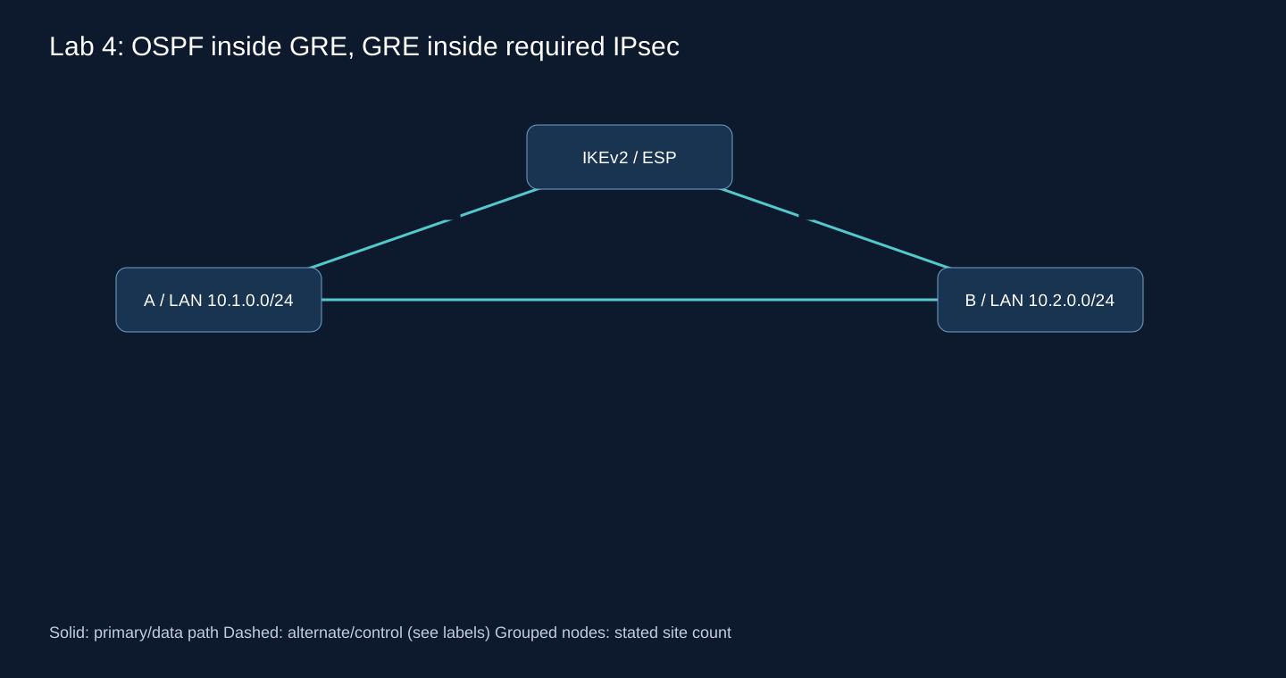
| Router | ether1 | ether2 LAN | LAB-GRE |
|---|---|---|---|
| A | 198.18.0.1/30 | 10.1.0.1/24 | 172.20.4.1/30 |
| B | 198.18.0.2/30 | 10.2.0.1/24 | 172.20.4.2/30 |
Directly connected underlay, no NAT in this lab. Explicit policy protects protocol 47 between endpoints in transport mode; clear GRE is dropped even if the IPsec SA fails. Both ends use the same replacement PSK. This avoids relying on an automatically generated legacy proposal behind ipsec-secret. The conservative 1400 inner MTU is a lab value, not a universal Internet PMTU.
Router 1
/ip address add address=198.18.0.1/30 interface=ether1
/ip address add address=10.1.0.1/24 interface=ether2
/interface gre add name=LAB-GRE local-address=198.18.0.1 remote-address=198.18.0.2 mtu=1400 allow-fast-path=no
/ip address add address=172.20.4.1/30 interface=LAB-GRE
/ip ipsec profile add name=LAB-IKE hash-algorithm=sha256 enc-algorithm=aes-256 dh-group=modp2048
/ip ipsec proposal add name=LAB-ESP auth-algorithms=sha256 enc-algorithms=aes-256-cbc pfs-group=modp2048
/ip ipsec peer add name=LAB-PEER address=198.18.0.2/32 local-address=198.18.0.1 exchange-mode=ike2 profile=LAB-IKE
/ip ipsec identity add peer=LAB-PEER auth-method=pre-shared-key secret="REPLACE_MATCHING_RANDOM_PSK"
/ip ipsec policy add peer=LAB-PEER src-address=198.18.0.1/32 dst-address=198.18.0.2/32 protocol=gre tunnel=no action=encrypt level=require proposal=LAB-ESP
/routing ospf instance add name=LAB-OSPF version=2 router-id=10.255.4.1
/routing ospf area add name=LAB-A0 instance=LAB-OSPF area-id=0.0.0.0
/routing ospf interface-template add area=LAB-A0 interfaces=LAB-GRE type=ptp cost=10
/routing ospf interface-template add area=LAB-A0 interfaces=ether2 passive
/ip firewall address-list add list=LAB-CORP address=10.0.0.0/8
/ip firewall filter add chain=input action=drop in-interface=ether1 protocol=gre ipsec-policy=in,none comment=LAB-no-clear-GRE
/ip firewall filter add chain=input action=accept connection-state=established,related comment=LAB-established
/ip firewall filter add chain=input action=drop connection-state=invalid comment=LAB-invalid
/ip firewall filter add chain=input action=accept protocol=icmp src-address-list=LAB-CORP comment=LAB-icmp
/ip firewall filter add chain=input action=accept in-interface=ether1 src-address=198.18.0.2 protocol=udp dst-port=500,4500 comment=LAB-IKE
/ip firewall filter add chain=input action=accept in-interface=ether1 src-address=198.18.0.2 protocol=ipsec-esp comment=LAB-ESP
/ip firewall filter add chain=input action=accept in-interface=ether1 src-address=198.18.0.2 protocol=gre ipsec-policy=in,ipsec comment=LAB-encrypted-GRE
/ip firewall filter add chain=input action=accept in-interface=LAB-GRE protocol=ospf comment=LAB-OSPF
/ip firewall filter add chain=input action=accept in-interface=LAB-GRE protocol=icmp comment=LAB-tunnel-icmp
/ip firewall filter add chain=input action=drop comment=LAB-input-default
/ip firewall filter add chain=forward action=accept connection-state=established,related comment=LAB-forward-established
/ip firewall filter add chain=forward action=drop connection-state=invalid comment=LAB-forward-invalid
/ip firewall filter add chain=forward action=accept src-address-list=LAB-CORP dst-address-list=LAB-CORP comment=LAB-corporate-only
/ip firewall filter add chain=forward action=drop comment=LAB-forward-default
Router 2
/ip address add address=198.18.0.2/30 interface=ether1
/ip address add address=10.2.0.1/24 interface=ether2
/interface gre add name=LAB-GRE local-address=198.18.0.2 remote-address=198.18.0.1 mtu=1400 allow-fast-path=no
/ip address add address=172.20.4.2/30 interface=LAB-GRE
/ip ipsec profile add name=LAB-IKE hash-algorithm=sha256 enc-algorithm=aes-256 dh-group=modp2048
/ip ipsec proposal add name=LAB-ESP auth-algorithms=sha256 enc-algorithms=aes-256-cbc pfs-group=modp2048
/ip ipsec peer add name=LAB-PEER address=198.18.0.1/32 local-address=198.18.0.2 exchange-mode=ike2 profile=LAB-IKE
/ip ipsec identity add peer=LAB-PEER auth-method=pre-shared-key secret="REPLACE_MATCHING_RANDOM_PSK"
/ip ipsec policy add peer=LAB-PEER src-address=198.18.0.2/32 dst-address=198.18.0.1/32 protocol=gre tunnel=no action=encrypt level=require proposal=LAB-ESP
/routing ospf instance add name=LAB-OSPF version=2 router-id=10.255.4.2
/routing ospf area add name=LAB-A0 instance=LAB-OSPF area-id=0.0.0.0
/routing ospf interface-template add area=LAB-A0 interfaces=LAB-GRE type=ptp cost=10
/routing ospf interface-template add area=LAB-A0 interfaces=ether2 passive
/ip firewall address-list add list=LAB-CORP address=10.0.0.0/8
/ip firewall filter add chain=input action=drop in-interface=ether1 protocol=gre ipsec-policy=in,none comment=LAB-no-clear-GRE
/ip firewall filter add chain=input action=accept connection-state=established,related comment=LAB-established
/ip firewall filter add chain=input action=drop connection-state=invalid comment=LAB-invalid
/ip firewall filter add chain=input action=accept protocol=icmp src-address-list=LAB-CORP comment=LAB-icmp
/ip firewall filter add chain=input action=accept in-interface=ether1 src-address=198.18.0.1 protocol=udp dst-port=500,4500 comment=LAB-IKE
/ip firewall filter add chain=input action=accept in-interface=ether1 src-address=198.18.0.1 protocol=ipsec-esp comment=LAB-ESP
/ip firewall filter add chain=input action=accept in-interface=ether1 src-address=198.18.0.1 protocol=gre ipsec-policy=in,ipsec comment=LAB-encrypted-GRE
/ip firewall filter add chain=input action=accept in-interface=LAB-GRE protocol=ospf comment=LAB-OSPF
/ip firewall filter add chain=input action=accept in-interface=LAB-GRE protocol=icmp comment=LAB-tunnel-icmp
/ip firewall filter add chain=input action=drop comment=LAB-input-default
/ip firewall filter add chain=forward action=accept connection-state=established,related comment=LAB-forward-established
/ip firewall filter add chain=forward action=drop connection-state=invalid comment=LAB-forward-invalid
/ip firewall filter add chain=forward action=accept src-address-list=LAB-CORP dst-address-list=LAB-CORP comment=LAB-corporate-only
/ip firewall filter add chain=forward action=drop comment=LAB-forward-default
Diagnostic commands
/ip ipsec active-peers print detail
/ip ipsec installed-sa print detail
/ip ipsec policy print detail
/routing ospf neighbor print detail
/ip route print detail where dst-address=10.2.0.0/24
/ping 10.2.0.1 src-address=10.1.0.1 count=10
Expected output — not observed
IKE peer established, inbound/outbound ESP counters increasing with traffic, one Full OSPF neighbor and remote LAN installed. Capture the underlay to verify payload is ESP (or NAT-T in a NAT variant), never clear GRE.
Failure test
# On A: simulate encryption failure, then restore
/ip ipsec peer disable LAB-PEER
# No clear-GRE forwarding is acceptable. Observe OSPF loss.
/ip ipsec peer enable LAB-PEER
Troubleshooting
No SA: PSK/proposal/peer reachability. SA but no Full: selectors must include GRE, equal inner MTU and protocol 89 input permission. Existing production NAT/FastTrack needs explicit exemptions before using this design.
Rollback
Re-enable LAB-PEER; to abort disable LAB-GRE and LAB-OSPF first so clear forwarding cannot become a fallback, then restore snapshots.
For a complete rollback, stop the test hosts and restore each VM’s pre-lab snapshot from the hypervisor console. An export is a reference, not an atomic restore. Never reset a production router to reproduce this lab.
Lab 5 — BGP over WireGuard, two hubs and two branches
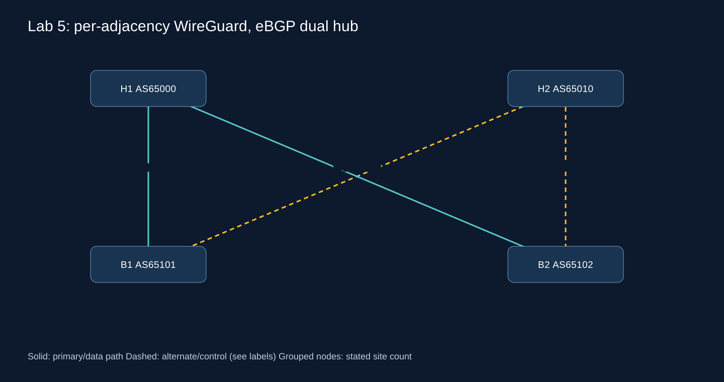
All ether1 ports share isolated 198.18.10.0/24: H1=.1, H2=.2, B1=.11, B2=.12. ether2 is the LAN. H1/H2 each have an isolated test service 10.100.0.0/24 with .1 as gateway; attach a separate .10 host behind each hub. They are equivalent test services, not a claim that a database can be duplicated by routing. Branch LANs are 10.1.0.0/24 and 10.2.0.0/24. No hub-to-hub link or branch-to-branch service is part of this lab.
| Adjacency | Hub WG IP | Branch WG IP | UDP port on both |
|---|---|---|---|
| H1-B1 | 172.21.1.1/30 | 172.21.1.2/30 | 52011 |
| H2-B1 | 172.22.1.1/30 | 172.22.1.2/30 | 52021 |
| H1-B2 | 172.21.2.1/30 | 172.21.2.2/30 | 52012 |
| H2-B2 | 172.22.2.1/30 | 172.22.2.2/30 | 52022 |
H1 interfaces — run before exchanging keys
/ip address add address=198.18.10.1/24 interface=ether1
/ip address add address=10.100.0.1/24 interface=ether2
/interface wireguard add name=LAB-H1B1 listen-port=52011 mtu=1420
/ip address add address=172.21.1.1/30 interface=LAB-H1B1
/interface wireguard add name=LAB-H1B2 listen-port=52012 mtu=1420
/ip address add address=172.21.2.1/30 interface=LAB-H1B2
/interface wireguard print detail
H2 interfaces — run before exchanging keys
/ip address add address=198.18.10.2/24 interface=ether1
/ip address add address=10.100.0.1/24 interface=ether2
/interface wireguard add name=LAB-H2B1 listen-port=52021 mtu=1420
/ip address add address=172.22.1.1/30 interface=LAB-H2B1
/interface wireguard add name=LAB-H2B2 listen-port=52022 mtu=1420
/ip address add address=172.22.2.1/30 interface=LAB-H2B2
/interface wireguard print detail
B1 interfaces — run before exchanging keys
/ip address add address=198.18.10.11/24 interface=ether1
/ip address add address=10.1.0.1/24 interface=ether2
/interface wireguard add name=LAB-H1B1 listen-port=52011 mtu=1420
/ip address add address=172.21.1.2/30 interface=LAB-H1B1
/interface wireguard add name=LAB-H2B1 listen-port=52021 mtu=1420
/ip address add address=172.22.1.2/30 interface=LAB-H2B1
/interface wireguard print detail
B2 interfaces — run before exchanging keys
/ip address add address=198.18.10.12/24 interface=ether1
/ip address add address=10.2.0.1/24 interface=ether2
/interface wireguard add name=LAB-H1B2 listen-port=52012 mtu=1420
/ip address add address=172.21.2.2/30 interface=LAB-H1B2
/interface wireguard add name=LAB-H2B2 listen-port=52022 mtu=1420
/ip address add address=172.22.2.2/30 interface=LAB-H2B2
/interface wireguard print detail
Collect the public key of every LAB-HxBy interface, not just one key per router. In the next blocks REPLACE_<router>_<adjacency>_KEY means the public key of that exact remote interface. On separate interfaces the same service prefix may map to two peers without ambiguous cryptokey selection.
H1 peers, BGP and firewall
/interface wireguard peers add interface=LAB-H1B1 public-key="REPLACE_B1_H1B1_KEY" endpoint-address=198.18.10.11 endpoint-port=52011 allowed-address=172.21.1.2/32,10.1.0.0/24 persistent-keepalive=25s
/interface wireguard peers add interface=LAB-H1B2 public-key="REPLACE_B2_H1B2_KEY" endpoint-address=198.18.10.12 endpoint-port=52012 allowed-address=172.21.2.2/32,10.2.0.0/24 persistent-keepalive=25s
/routing bgp instance add name=LAB-BGP as=65000 router-id=10.255.10.1
/ip firewall address-list add list=LAB-ORIGIN address=10.100.0.0/24
/routing filter rule add chain=LAB-IN-H1B1 rule="if (dst == 10.1.0.0/24) { accept; } else { reject; }"
/routing filter rule add chain=LAB-OUT-H1B1 rule="if (dst == 10.100.0.0/24) { accept; } else { reject; }"
/routing bgp connection add name=LAB-H1B1 instance=LAB-BGP local.role=ebgp local.address=172.21.1.1 remote.address=172.21.1.2 remote.as=65101 afi=ip input.filter=LAB-IN-H1B1 input.limit-process-routes-ipv4=10 output.filter-chain=LAB-OUT-H1B1 output.network=LAB-ORIGIN output.network-blackhole=no hold-time=30s keepalive-time=10s
/routing filter rule add chain=LAB-IN-H1B2 rule="if (dst == 10.2.0.0/24) { accept; } else { reject; }"
/routing filter rule add chain=LAB-OUT-H1B2 rule="if (dst == 10.100.0.0/24) { accept; } else { reject; }"
/routing bgp connection add name=LAB-H1B2 instance=LAB-BGP local.role=ebgp local.address=172.21.2.1 remote.address=172.21.2.2 remote.as=65102 afi=ip input.filter=LAB-IN-H1B2 input.limit-process-routes-ipv4=10 output.filter-chain=LAB-OUT-H1B2 output.network=LAB-ORIGIN output.network-blackhole=no hold-time=30s keepalive-time=10s
/ip firewall address-list add list=LAB-CORP address=10.100.0.0/24
/ip firewall address-list add list=LAB-CORP address=10.1.0.0/24
/ip firewall address-list add list=LAB-CORP address=10.2.0.0/24

/ip firewall filter add chain=input action=accept connection-state=established,related comment=LAB-established
/ip firewall filter add chain=input action=drop connection-state=invalid comment=LAB-invalid
/ip firewall filter add chain=input action=accept protocol=icmp src-address-list=LAB-CORP comment=LAB-icmp
/ip firewall filter add chain=input action=accept in-interface=ether1 src-address=198.18.10.11 protocol=udp dst-port=52011 comment=LAB-WG
/ip firewall filter add chain=input action=accept in-interface=LAB-H1B1 src-address=172.21.1.2 protocol=tcp dst-port=179 comment=LAB-BGP
/ip firewall filter add chain=input action=accept in-interface=LAB-H1B1 protocol=icmp comment=LAB-WG-icmp
/ip firewall filter add chain=input action=accept in-interface=ether1 src-address=198.18.10.12 protocol=udp dst-port=52012 comment=LAB-WG
/ip firewall filter add chain=input action=accept in-interface=LAB-H1B2 src-address=172.21.2.2 protocol=tcp dst-port=179 comment=LAB-BGP
/ip firewall filter add chain=input action=accept in-interface=LAB-H1B2 protocol=icmp comment=LAB-WG-icmp
/ip firewall filter add chain=input action=drop comment=LAB-input-default
/ip firewall filter add chain=forward action=accept connection-state=established,related comment=LAB-forward-established
/ip firewall filter add chain=forward action=drop connection-state=invalid comment=LAB-forward-invalid
/ip firewall filter add chain=forward action=accept src-address-list=LAB-CORP dst-address-list=LAB-CORP comment=LAB-corporate-only
/ip firewall filter add chain=forward action=drop comment=LAB-forward-default
H2 peers, BGP and firewall
/interface wireguard peers add interface=LAB-H2B1 public-key="REPLACE_B1_H2B1_KEY" endpoint-address=198.18.10.11 endpoint-port=52021 allowed-address=172.22.1.2/32,10.1.0.0/24 persistent-keepalive=25s
/interface wireguard peers add interface=LAB-H2B2 public-key="REPLACE_B2_H2B2_KEY" endpoint-address=198.18.10.12 endpoint-port=52022 allowed-address=172.22.2.2/32,10.2.0.0/24 persistent-keepalive=25s
/routing bgp instance add name=LAB-BGP as=65010 router-id=10.255.10.2
/ip firewall address-list add list=LAB-ORIGIN address=10.100.0.0/24
/routing filter rule add chain=LAB-IN-H2B1 rule="if (dst == 10.1.0.0/24) { accept; } else { reject; }"
/routing filter rule add chain=LAB-OUT-H2B1 rule="if (dst == 10.100.0.0/24) { accept; } else { reject; }"
/routing bgp connection add name=LAB-H2B1 instance=LAB-BGP local.role=ebgp local.address=172.22.1.1 remote.address=172.22.1.2 remote.as=65101 afi=ip input.filter=LAB-IN-H2B1 input.limit-process-routes-ipv4=10 output.filter-chain=LAB-OUT-H2B1 output.network=LAB-ORIGIN output.network-blackhole=no hold-time=30s keepalive-time=10s
/routing filter rule add chain=LAB-IN-H2B2 rule="if (dst == 10.2.0.0/24) { accept; } else { reject; }"
/routing filter rule add chain=LAB-OUT-H2B2 rule="if (dst == 10.100.0.0/24) { accept; } else { reject; }"
/routing bgp connection add name=LAB-H2B2 instance=LAB-BGP local.role=ebgp local.address=172.22.2.1 remote.address=172.22.2.2 remote.as=65102 afi=ip input.filter=LAB-IN-H2B2 input.limit-process-routes-ipv4=10 output.filter-chain=LAB-OUT-H2B2 output.network=LAB-ORIGIN output.network-blackhole=no hold-time=30s keepalive-time=10s
/ip firewall address-list add list=LAB-CORP address=10.100.0.0/24
/ip firewall address-list add list=LAB-CORP address=10.1.0.0/24
/ip firewall address-list add list=LAB-CORP address=10.2.0.0/24

/ip firewall filter add chain=input action=accept connection-state=established,related comment=LAB-established
/ip firewall filter add chain=input action=drop connection-state=invalid comment=LAB-invalid
/ip firewall filter add chain=input action=accept protocol=icmp src-address-list=LAB-CORP comment=LAB-icmp
/ip firewall filter add chain=input action=accept in-interface=ether1 src-address=198.18.10.11 protocol=udp dst-port=52021 comment=LAB-WG
/ip firewall filter add chain=input action=accept in-interface=LAB-H2B1 src-address=172.22.1.2 protocol=tcp dst-port=179 comment=LAB-BGP
/ip firewall filter add chain=input action=accept in-interface=LAB-H2B1 protocol=icmp comment=LAB-WG-icmp
/ip firewall filter add chain=input action=accept in-interface=ether1 src-address=198.18.10.12 protocol=udp dst-port=52022 comment=LAB-WG
/ip firewall filter add chain=input action=accept in-interface=LAB-H2B2 src-address=172.22.2.2 protocol=tcp dst-port=179 comment=LAB-BGP
/ip firewall filter add chain=input action=accept in-interface=LAB-H2B2 protocol=icmp comment=LAB-WG-icmp
/ip firewall filter add chain=input action=drop comment=LAB-input-default
/ip firewall filter add chain=forward action=accept connection-state=established,related comment=LAB-forward-established
/ip firewall filter add chain=forward action=drop connection-state=invalid comment=LAB-forward-invalid
/ip firewall filter add chain=forward action=accept src-address-list=LAB-CORP dst-address-list=LAB-CORP comment=LAB-corporate-only
/ip firewall filter add chain=forward action=drop comment=LAB-forward-default
B1 peers, BGP and firewall
/interface wireguard peers add interface=LAB-H1B1 public-key="REPLACE_H1_H1B1_KEY" endpoint-address=198.18.10.1 endpoint-port=52011 allowed-address=172.21.1.1/32,10.100.0.0/24 persistent-keepalive=25s
/interface wireguard peers add interface=LAB-H2B1 public-key="REPLACE_H2_H2B1_KEY" endpoint-address=198.18.10.2 endpoint-port=52021 allowed-address=172.22.1.1/32,10.100.0.0/24 persistent-keepalive=25s
/routing bgp instance add name=LAB-BGP as=65101 router-id=10.255.10.11
/ip firewall address-list add list=LAB-ORIGIN address=10.1.0.0/24
/routing filter rule add chain=LAB-IN-H1B1 rule="if (dst == 10.100.0.0/24) { set bgp-local-pref 200; accept; } else { reject; }"
/routing filter rule add chain=LAB-OUT-H1B1 rule="if (dst == 10.1.0.0/24) { accept; } else { reject; }"
/routing bgp connection add name=LAB-H1B1 instance=LAB-BGP local.role=ebgp local.address=172.21.1.2 remote.address=172.21.1.1 remote.as=65000 afi=ip input.filter=LAB-IN-H1B1 input.limit-process-routes-ipv4=10 output.filter-chain=LAB-OUT-H1B1 output.network=LAB-ORIGIN output.network-blackhole=no hold-time=30s keepalive-time=10s
/routing filter rule add chain=LAB-IN-H2B1 rule="if (dst == 10.100.0.0/24) { set bgp-local-pref 100; accept; } else { reject; }"
/routing filter rule add chain=LAB-OUT-H2B1 rule="if (dst == 10.1.0.0/24) { accept; } else { reject; }"
/routing bgp connection add name=LAB-H2B1 instance=LAB-BGP local.role=ebgp local.address=172.22.1.2 remote.address=172.22.1.1 remote.as=65010 afi=ip input.filter=LAB-IN-H2B1 input.limit-process-routes-ipv4=10 output.filter-chain=LAB-OUT-H2B1 output.network=LAB-ORIGIN output.network-blackhole=no hold-time=30s keepalive-time=10s
/ip firewall address-list add list=LAB-CORP address=10.100.0.0/24
/ip firewall address-list add list=LAB-CORP address=10.1.0.0/24
/ip firewall address-list add list=LAB-CORP address=10.2.0.0/24

/ip firewall filter add chain=input action=accept connection-state=established,related comment=LAB-established
/ip firewall filter add chain=input action=drop connection-state=invalid comment=LAB-invalid
/ip firewall filter add chain=input action=accept protocol=icmp src-address-list=LAB-CORP comment=LAB-icmp
/ip firewall filter add chain=input action=accept in-interface=ether1 src-address=198.18.10.1 protocol=udp dst-port=52011 comment=LAB-WG
/ip firewall filter add chain=input action=accept in-interface=LAB-H1B1 src-address=172.21.1.1 protocol=tcp dst-port=179 comment=LAB-BGP
/ip firewall filter add chain=input action=accept in-interface=LAB-H1B1 protocol=icmp comment=LAB-WG-icmp
/ip firewall filter add chain=input action=accept in-interface=ether1 src-address=198.18.10.2 protocol=udp dst-port=52021 comment=LAB-WG
/ip firewall filter add chain=input action=accept in-interface=LAB-H2B1 src-address=172.22.1.1 protocol=tcp dst-port=179 comment=LAB-BGP
/ip firewall filter add chain=input action=accept in-interface=LAB-H2B1 protocol=icmp comment=LAB-WG-icmp
/ip firewall filter add chain=input action=drop comment=LAB-input-default
/ip firewall filter add chain=forward action=accept connection-state=established,related comment=LAB-forward-established
/ip firewall filter add chain=forward action=drop connection-state=invalid comment=LAB-forward-invalid
/ip firewall filter add chain=forward action=accept src-address-list=LAB-CORP dst-address-list=LAB-CORP comment=LAB-corporate-only
/ip firewall filter add chain=forward action=drop comment=LAB-forward-default
B2 peers, BGP and firewall
/interface wireguard peers add interface=LAB-H1B2 public-key="REPLACE_H1_H1B2_KEY" endpoint-address=198.18.10.1 endpoint-port=52012 allowed-address=172.21.2.1/32,10.100.0.0/24 persistent-keepalive=25s
/interface wireguard peers add interface=LAB-H2B2 public-key="REPLACE_H2_H2B2_KEY" endpoint-address=198.18.10.2 endpoint-port=52022 allowed-address=172.22.2.1/32,10.100.0.0/24 persistent-keepalive=25s
/routing bgp instance add name=LAB-BGP as=65102 router-id=10.255.10.12
/ip firewall address-list add list=LAB-ORIGIN address=10.2.0.0/24
/routing filter rule add chain=LAB-IN-H1B2 rule="if (dst == 10.100.0.0/24) { set bgp-local-pref 200; accept; } else { reject; }"
/routing filter rule add chain=LAB-OUT-H1B2 rule="if (dst == 10.2.0.0/24) { accept; } else { reject; }"
/routing bgp connection add name=LAB-H1B2 instance=LAB-BGP local.role=ebgp local.address=172.21.2.2 remote.address=172.21.2.1 remote.as=65000 afi=ip input.filter=LAB-IN-H1B2 input.limit-process-routes-ipv4=10 output.filter-chain=LAB-OUT-H1B2 output.network=LAB-ORIGIN output.network-blackhole=no hold-time=30s keepalive-time=10s
/routing filter rule add chain=LAB-IN-H2B2 rule="if (dst == 10.100.0.0/24) { set bgp-local-pref 100; accept; } else { reject; }"
/routing filter rule add chain=LAB-OUT-H2B2 rule="if (dst == 10.2.0.0/24) { accept; } else { reject; }"
/routing bgp connection add name=LAB-H2B2 instance=LAB-BGP local.role=ebgp local.address=172.22.2.2 remote.address=172.22.2.1 remote.as=65010 afi=ip input.filter=LAB-IN-H2B2 input.limit-process-routes-ipv4=10 output.filter-chain=LAB-OUT-H2B2 output.network=LAB-ORIGIN output.network-blackhole=no hold-time=30s keepalive-time=10s
/ip firewall address-list add list=LAB-CORP address=10.100.0.0/24
/ip firewall address-list add list=LAB-CORP address=10.1.0.0/24
/ip firewall address-list add list=LAB-CORP address=10.2.0.0/24

/ip firewall filter add chain=input action=accept connection-state=established,related comment=LAB-established
/ip firewall filter add chain=input action=drop connection-state=invalid comment=LAB-invalid
/ip firewall filter add chain=input action=accept protocol=icmp src-address-list=LAB-CORP comment=LAB-icmp
/ip firewall filter add chain=input action=accept in-interface=ether1 src-address=198.18.10.1 protocol=udp dst-port=52012 comment=LAB-WG
/ip firewall filter add chain=input action=accept in-interface=LAB-H1B2 src-address=172.21.2.1 protocol=tcp dst-port=179 comment=LAB-BGP
/ip firewall filter add chain=input action=accept in-interface=LAB-H1B2 protocol=icmp comment=LAB-WG-icmp
/ip firewall filter add chain=input action=accept in-interface=ether1 src-address=198.18.10.2 protocol=udp dst-port=52022 comment=LAB-WG
/ip firewall filter add chain=input action=accept in-interface=LAB-H2B2 src-address=172.22.2.1 protocol=tcp dst-port=179 comment=LAB-BGP
/ip firewall filter add chain=input action=accept in-interface=LAB-H2B2 protocol=icmp comment=LAB-WG-icmp
/ip firewall filter add chain=input action=drop comment=LAB-input-default
/ip firewall filter add chain=forward action=accept connection-state=established,related comment=LAB-forward-established
/ip firewall filter add chain=forward action=drop connection-state=invalid comment=LAB-forward-invalid
/ip firewall filter add chain=forward action=accept src-address-list=LAB-CORP dst-address-list=LAB-CORP comment=LAB-corporate-only
/ip firewall filter add chain=forward action=drop comment=LAB-forward-default
Diagnostic commands
/interface wireguard peers print detail
/routing bgp session print detail
/routing route print detail where dst-address=10.100.0.0/24
/ping 10.100.0.10 src-address=10.1.0.1 interval=200ms count=100
Expected output — not observed
B1 has two candidates for 10.100.0.0/24; the path from H1 has LP200 and wins over LP100. Disabling its WG path must eventually select H2. Expect existing TCP sessions to fail unless the service and firewall architecture explicitly preserve state.
Failure test
# On B1 only:
/interface wireguard disable LAB-H1B1
# Measure hold-timer detection, route change and traffic recovery; restore:
/interface wireguard enable LAB-H1B1
Troubleshooting
A handshake without BGP: TCP input ACL, tunnel source and matching ASN. BGP up without traffic: allowed source service prefix, active LAN route, export filter and return path. This lab tests tunnel failure, not ISP path pinning; production dual-WAN needs separate outer route tables/pinning.
Rollback
Re-enable LAB-H1B1, then disable LAB-* BGP connections to stop announcements before restoring the four snapshots.
For a complete rollback, stop the test hosts and restore each VM’s pre-lab snapshot from the hypervisor console. An export is a reference, not an atomic restore. Never reset a production router to reproduce this lab.
Lab 6 — IOS XE and RouterOS OSPF interoperability
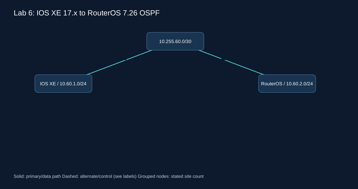
Use a routing-capable IOS XE 17.x image with GigabitEthernet1/2, and a blank RouterOS 7.26 VM with ether1/2. Gi1↔ether1 is 10.255.60.0/30. Gi2 is 10.60.1.1/24; ether2 is 10.60.2.1/24. Hosts are .10 with .1 gateway. IOS XE model licensing must permit OSPF; interface names must be mapped to the actual image before pasting. Authentication is omitted only on this isolated transit.
Cisco IOS XE
configure terminal
ip routing
ip access-list extended LAB-TRANSIT
 permit ospf host 10.255.60.2 any
 permit icmp 10.0.0.0 0.255.255.255 any
 permit ip 10.60.2.0 0.0.0.255 10.60.1.0 0.0.0.255
 deny ip any any log
interface GigabitEthernet1
 ip address 10.255.60.1 255.255.255.252
 ip ospf network point-to-point
 ip ospf 60 area 0
 ip access-group LAB-TRANSIT in
 no shutdown
interface GigabitEthernet2
 ip address 10.60.1.1 255.255.255.0
 ip ospf 60 area 0
 no shutdown
router ospf 60
 router-id 10.255.60.1
 passive-interface default
 no passive-interface GigabitEthernet1
end
MikroTik RouterOS
/ip address add address=10.255.60.2/30 interface=ether1
/ip address add address=10.60.2.1/24 interface=ether2
/routing ospf instance add name=LAB-OSPF version=2 router-id=10.255.60.2
/routing ospf area add name=LAB-A0 instance=LAB-OSPF area-id=0.0.0.0
/routing ospf interface-template add area=LAB-A0 interfaces=ether1 type=ptp cost=10
/routing ospf interface-template add area=LAB-A0 interfaces=ether2 passive
/ip firewall address-list add list=LAB-CORP address=10.60.1.0/24
/ip firewall address-list add list=LAB-CORP address=10.60.2.0/24
/ip firewall address-list add list=LAB-CORP address=10.255.60.0/30

/ip firewall filter add chain=input action=accept connection-state=established,related comment=LAB-established
/ip firewall filter add chain=input action=drop connection-state=invalid comment=LAB-invalid
/ip firewall filter add chain=input action=accept protocol=icmp src-address-list=LAB-CORP comment=LAB-icmp
/ip firewall filter add chain=input action=accept protocol=ospf in-interface=ether1 src-address=10.255.60.1 comment=LAB-OSPF
/ip firewall filter add chain=input action=drop comment=LAB-input-default
/ip firewall filter add chain=forward action=accept connection-state=established,related comment=LAB-forward-established
/ip firewall filter add chain=forward action=drop connection-state=invalid comment=LAB-forward-invalid
/ip firewall filter add chain=forward action=accept src-address-list=LAB-CORP dst-address-list=LAB-CORP comment=LAB-corporate-only
/ip firewall filter add chain=forward action=drop comment=LAB-forward-default
Cisco diagnostics
show version
show ip ospf neighbor
show ip ospf interface GigabitEthernet1
show ip route ospf
show access-lists LAB-TRANSIT
ping 10.60.2.1 source 10.60.1.1
Diagnostic commands
/system resource print
/routing ospf neighbor print detail
/ip route print detail where dst-address=10.60.1.0/24
/ip firewall filter print stats
/ping 10.60.1.1 src-address=10.60.2.1 count=10
Expected output — not observed
One Full point-to-point adjacency, each remote /24 as OSPF, working source-specific ping. LAN interfaces send no OSPF hellos. Compare MTU, 10/40 default Hello/Dead behavior and area 0 before accepting interoperability.
Failure test
# RouterOS link failure and restore:
/interface ethernet disable ether1
/interface ethernet enable ether1
Troubleshooting
No Full: check packet direction, ACL hits, MTU and matching network type. A broadcast/ptp mismatch can produce misleading states. The Cisco transit ACL is a narrow lab rule, not a complete production control-plane policy.
Rollback
Restore the two pre-lab VM snapshots. On a physical test device remove only process 60, LAB-TRANSIT binding/ACL and the documented test addresses after retaining console access.
For a complete rollback, stop the test hosts and restore each VM’s pre-lab snapshot from the hypervisor console. An export is a reference, not an atomic restore. Never reset a production router to reproduce this lab.
Failure runbook: observe the route and the packet
The commands below target RouterOS 7.26 unless marked IOS XE. “Expected” means the evidence to look for, not captured output. First record source, destination, VRF/table and time. Ping from the router’s WAN address can succeed while a client subnet fails. Check both directions and preserve counters before changing configuration. Do not clear every session, disable the firewall or enable blanket redistribution as a diagnostic shortcut.
| Problem | Root cause to investigate | Diagnostic command | Expected evidence | Resolution |
|---|---|---|---|---|
| Primary Internet loss | Last mile or upstream failed; modem may still answer. | /ip route print detail; /tool traceroute <probe> | Pinned probe fails; primary route should become ineligible. | Correct tracking and ISP-bound probes; test backup bandwidth/return path. |
| Backup Internet loss | Dormant path failed unnoticed. | /ping <backup-probe> routing-table=<backup-table> | Probe fails in backup table while primary service is healthy. | Repair ISP2 and alarm on candidate-path health, not only active route. |
| Tunnel down | Keys, endpoint route, UDP/ESP or peer reachability. | /interface wireguard peers print detail; /ip ipsec active-peers print | No new handshake/SA after generating traffic; compare rx/tx. | Fix outer reachability and identity before inner routing. |
| Central router loss | Device/power failure or control-plane overload. | /routing bgp session print detail; /routing ospf neighbor print detail | All sessions to one hub disappear, diverse hub remains. | Activate tested second hub; inspect shared power/ISP dependencies. |
| Data-center loss | Site unavailable; service readiness and routes diverge. | /routing route print detail where dst-address=<service-prefix> | Failed DC route withdrawn; DR route exists only if service ready. | Coordinate DNS/app/data recovery and conditional advertisement. |
| OSPF INIT | One-way Hello, multicast peer mapping, firewall or wrong network model. | /routing ospf neighbor print detail; /ip firewall filter print stats | Neighbor lists local ID only after bidirectional exchange; INIT lacks it. | Verify both packet directions and WG peer mapping; align network type. |
| OSPF EXSTART / EXCHANGE | MTU mismatch, duplicate ID or DD packet loss. | /routing ospf interface print detail; /interface print detail | MTU differs or DD exchange repeats without Full. | Fix effective end-to-end MTU/IDs and loss; do not hide a real MTU fault with ignore knobs. |
| BGP Active | TCP cannot complete; wrong source/ASN/TTL/authentication. | /routing bgp connection print detail; /log print where topics~"bgp" | Repeated connect attempts, notifications or no SYN response. | Verify remote IP/local source, TCP179, ASN and single/multihop settings. |
| BGP Established, zero routes | AFI mismatch, no active origin, restrictive filter or unresolved next hop. | /routing route print detail; /routing filter rule print detail | Differentiate absent, filtered and inactive routes. | Correct exact origin route and filters; confirm next-hop resolution. |
| Wrong advertisement | Overbroad network list, redistribution or aggregate. | /routing bgp connection print detail; /routing filter rule print detail | Unexpected default/more-specific accepted by peer. | Withdraw only erroneous prefix, apply allowlist and prefix budget, inspect downstream propagation. |
| Routing loop | Mutual defaults, recursion or route feedback. | /tool traceroute <destination> src-address=<client-gateway> | Repeated hops/TTL exhaustion; compare route source on each hop. | Remove feedback at designated boundary; apply tags/prefix filters and valid summaries. |
| Asymmetric routing | Independent forward/return preferences or ECMP through different firewalls. | /tool traceroute <remote>; /ip firewall connection print | SYN one way, return through other state domain; invalid counters rise. | Align policy or use a supported state-sharing design; do not globally accept invalid traffic. |
| Incorrect redistribution | Two-way imports without ownership/tags/metric plan. | /routing ospf lsa print; /routing filter rule print detail | Same prefix returns as external via another boundary. | Use one controlled boundary or explicit anti-feedback filters and tags. |
| Overlapping subnets | Acquisition or unmanaged address allocation. | /ip address print; /ip vrf print; /ip route print detail | Same prefix represents different hosts; longest-prefix cannot distinguish identity. | Renumber when possible; isolate VRFs and deliberate NAT/shared-service translation if needed. |
| MTU / MSS | Encapsulation, PMTUD blocked or unequal interface MTU. | /ping <remote> size=1300 do-not-fragment=yes; /interface print detail | Small packets pass, larger DF packets fail; find actual threshold. | Compute stack overhead, permit PMTUD ICMP/ICMPv6; clamp TCP MSS only where justified. |
| Route flapping | Unstable radio/ISP, overaggressive timers or recurring automation. | /log print; /routing bgp session print detail | Repeated adjacency transitions correlate with interface/probe events. | Fix transport; add measured hold-down/debounce. Avoid blind Internet-wide damping policies. |
| Packet loss | Congestion, RF, CPU encryption saturation, policing or errors. | /interface print stats; /tool profile; /ping <remote> count=100 | Drops/errors/CPU correlate with load; route may remain stable. | Capacity/QoS/RF repair; routing change only if a better usable path exists. |
| CGNAT | Inbound mapping unavailable, UDP state timeout or NAT rebinding. | /interface wireguard peers print detail; /tool traceroute <hub-public> | Outbound initiated traffic restores mapping; direct inbound peer cannot reach spoke. | Public reachable hub, spoke initiation, appropriate keepalive or provider public service. |
| BFD session failure | Mode/VRF/address mismatch, blocked UDP, jitter or CPU scheduling. | /routing bfd session print detail; /tool profile | BFD down while normal ping can still pass; correlate timing. | Align supported BFD mode/VRF and firewall; increase timers based on measurements. |
| Incorrect firewall | Input confused with forward, interface list or rule-order mistake. | /ip firewall filter print stats; /ip firewall raw print stats | Specific drop counter grows during controlled traffic. | Add narrowly scoped rule before the matching drop; retain management access. |
| FastTrack interference | FastTracked flows bypass facilities required by IPsec/PBR/queues/VRF design. | /ip firewall filter print stats; /ip firewall connection print detail | New/slow-path packets work but established tracked flows diverge. | Exclude affected flows before FastTrack; retest new connections and both directions. |
| IPv6 route failures | Missing AF, link-local scope, ICMPv6/ND blocked or incomplete return prefix. | /ipv6 route print detail; /ipv6 neighbor print; /routing ospf neighbor print detail | IPv4 works while IPv6 next hop/ND/AF is absent or filtered. | Validate IPv6 end-to-end separately; permit required ICMPv6 and scope next hop to interface. |
Follow one organization from two to five hundred branches
| Stage | Pressure / is migration necessary? | Change / keep | Risk and staged method |
|---|---|---|---|
| 2: static | Two stable routes; no migration needed. | Keep addressing, encrypted transport and explicit return routes. | Validate backup/restore and document single path before adding complexity. |
| 5: two tunnels | Manual failover and probe dependencies; dynamic optional. | Add tracked/floating routes, pinned endpoints and monitoring; keep LAN blocks. | Probe may escape through backup. Test remote black hole and recovery, not only cable pull. |
| 10: dynamic | Frequent route edits/alternates may justify OSPF; number alone does not. | Add transit adjacencies, passive LANs and unique IDs; keep tunnels/IP plan. | Static may mask OSPF due to lower distance. Pilot one prefix, inspect LSDB and FIB, then adjust only its static preference. |
| 20: two DCs | Independent service placement/DR policy; not merely route volume. | Add service ownership, dual hubs and boundary filtering; retain healthy local OSPF. | Wrong aggregate sends traffic to unready DR. Test application move and return path before broad preference change. |
| 50: WAN redundancy | Heterogeneous paths and policies; hybrid may now reduce coupling. | Introduce BGP on WAN edges, exact exports; keep IGP inside sites. | Redistribution feedback and changed distances. Parallel canary prefixes, tags and rollback static routes with explicit owners. |
| 100: regional hubs | Latency, encryption capacity and failure ownership justify regions. | Regional policy/summaries, automation and optional RRs for iBGP; keep branch LAN templates. | Summary can hide missing child routes. Move one region, test hub failure at full regional load. |
| 500: multi-region | Cross-border/DC/cloud/security failures need bounded domains. | Regional BGP/VRFs and local hierarchical IGP; retain supported transports and allocations. | Mass deployment or leak can be global. Canary, batches, route budgets, route diff gates and tested regional rollback. |
Static to OSPF without a blind cutover
Export the current route/next-hop inventory and record source-specific traffic tests. Establish OSPF only on intended transit interfaces, verify Full and the LSDB, then compare candidate routes before changing the active path. A lower-distance static can remain active while OSPF is learned. Move one approved prefix by changing its static preference or removing only that route, test forward/return/application traffic, then proceed in batches. Keep a timed rollback plan and console access; do not redistribute every connected WAN network to make the table look complete.
OSPF to BGP or hybrid: move the boundary, not every router
Define an owner and allowed direction for every prefix. Add BGP at WAN edges in parallel with a deliberately worse preference or isolated test prefix/table. Compare received, accepted and active routes separately. Limit OSPF↔BGP redistribution to designed borders with tags and deny-return rules; often explicit network origination/defaults avoid broad redistribution entirely. Change one site’s import/export preference together with its return path. Verify failures and rollback before the next site. Administrative distance is vendor-specific and is evaluated only after longest-prefix matching; a more-specific route can defeat a supposedly preferred aggregate.
Why protocol preference values cannot be copied between vendors
The organization changes the architecture, even at the same branch count
| Organization | Real design driver | Conditional architecture |
|---|---|---|
| Chain stores | POS continuity, local breakout and rapid provisioning | Templated static for simple leaves; BGP/SD-WAN for dual paths and centrally governed access. |
| Bank / finance | Auditable segmentation, independent paths and strict DR | VRF-separated BGP WAN, encrypted transport, restricted management and verified stateful failover. |
| Manufacturing company | ERP/logistics plus plant autonomy | Local IGP and filtered WAN boundary; keep production services running during HQ isolation. |
| Industrial plants | OT safety, maintenance windows and legacy controllers | Static isolated cells, routed transport IGP and firewall-mediated shared services. |
| Distribution / logistics | Warehouse scanning, mobile connectivity and variable access | Resilient hub VPN, BGP policy when multi-path; measure cellular loss/CGNAT before aggressive timers. |
| Hospital / healthcare | Clinical service continuity and medical-device isolation | Redundant local core, bounded routing domains, explicit medical/shared-service imports and tested DR. |
| University / campus | Large local topology, research tenants and guest access | OSPF or supported IS-IS campus core; VRFs; BGP at external/provider boundaries. |
| Multiple DCs | Service placement, east-west bandwidth and fabric semantics | Local fabric underlay; EVPN only where required/supported; WAN BGP separate from fabric failure domains. |
| Hybrid cloud company | Route propagation, cloud quotas and egress paths | BGP cloud edges, separated attachment tables and explicit return routing; cloud services are not IGP replacements. |
| ISP | Internet policy, customer isolation and label transport | BGP Internet/customer edge, supported OSPF/IS-IS core, MP-BGP VPNs and Internet RPKI/filters. |
| International enterprise | Jurisdictions, regional autonomy and cross-border failures | Regional BGP/VRF boundaries with controlled shared-service access and diverse cloud/DC connections. |
| Mixed Cisco / MikroTik | Feature intersection, operator skill and consistent intent | OSPF/BGP at interop boundaries; preserve healthy vendor-specific local domains behind explicit filters. |
Cloud routing: services manage attachments, BGP exchanges prefixes
A cloud routing service is a managed connectivity and route-table product. BGP is one protocol that service may expose at an edge. A VPN tunnel being UP does not mean a VPC/VNet route table, security group, network ACL or on-premises firewall permits the application. In multi-cloud, equal-looking RFC1918 space, different transit semantics and competing defaults cause more problems than the BGP session itself.
| Service | Routing boundary | Design check |
|---|---|---|
| Site-to-Site / Cloud VPN | IPsec service; static or BGP depending on provider/gateway | Two tunnels and supported routing mode are not two independent last miles; check IPv6 and quotas separately. |
| AWS Transit Gateway | Regional transit hub with attachment associations/propagations | Association selects the attachment lookup table; propagation installs learned routes into selected tables. Use separate trust-domain tables and approved propagation. |
| AWS Direct Connect | Dedicated connectivity via VIFs and BGP, with gateway model appropriate to VPC/TGW | Select private/transit/public VIF intentionally; diverse connections and VPN backup require planned path preference. Dedicated does not imply IPsec encryption. |
| Azure VPN Gateway | BGP optional on supported route-based VPN gateways | Verify SKU, active-active behavior, supported ASN/APIPA choices, route limits and custom device requirements. |
| Azure ExpressRoute | Private connectivity with BGP peerings; service-specific routing domains | Private peering, redundant sessions, advertised prefixes and gateway coexistence need explicit design; VPN/ExpressRoute transit is not assumed. |
| Hybrid / Multi-Cloud | Organization edge and each cloud transit service have separate route policy | Filter at controllable boundaries, prevent unintended cloud-to-cloud transit and double-default loops; test DNS and data paths. |
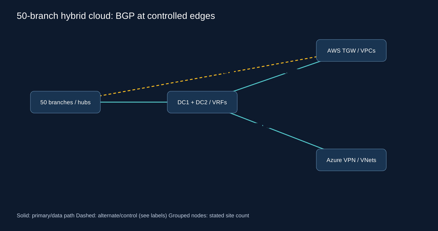
For the 50-branch example, allocate non-overlapping branch, DC, AWS and Azure blocks first. Use redundant DC/regional cloud edges rather than creating 50 independent unmanaged cloud gateways. In AWS, associate branch VPN attachments with a branch table and propagate only approved DC/VPC routes into it; associate service attachments with their required return tables. In Azure, inspect effective routes and the supported gateway propagation/transit model. On-premises BGP filters accept only assigned cloud prefixes and advertise only approved corporate blocks. A local Internet default must not accidentally become cloud transit.
Fail Direct Connect/ExpressRoute, then one VPN tunnel, then a DC, and inspect both customer and cloud route tables each time. A static route can override or black-hole a learned path under a provider’s specific precedence rules. Do not assume BGP Local Preference from your router controls the cloud service’s entire route-selection order. Record regional quotas and current service limits during deployment, rather than embedding a permanent numeric limit in this article.
AWS TGW route-table associations and propagation
AWS Site-to-Site VPN static and dynamic setup
AWS Direct Connect service model
Azure VPN Gateway BGP requirements
Operations: keep intended state separate from observed state
I would use NetBox as a Source of Truth for approved sites, devices, prefixes, VRFs, interfaces and ASNs where its data model fits. Model tunnel endpoints and underlay ownership through interfaces/IPs and validated custom fields or an appropriate maintained plugin. NetBox does not discover the correct design by itself. Git holds reviewed templates and intended changes; Oxidized captures observed device configurations. An observed backup is evidence, not automatic authorization to make that configuration the desired state.
| Tool / signal | Practical role | Acceptance / alert |
|---|---|---|
| NetBox | Site BR-021 → region → routers → interfaces → prefixes → VRF → ASN; assign owner and source of underlay. | Reject duplicate/overlapping allocations outside approved VRFs before rendering. |
| Ansible + Git | Render vendor-specific intent, review diff, canary one site, verify pre/post state then batch rollout. | Stop on unexpected prefix count/next hop, unavailable backup or lost management. |
| Oxidized / Configuration Backup | Scheduled config capture with restricted repository and tested restore; secrets protected. | Alert on unapproved route/filter/tunnel changes; preserve the before version. |
| Zabbix | SNMP/API/agent items and triggers for interface, session and resource health with dependency-aware alerts. | Correlate many spoke-down alarms with a single hub/ISP failure. |
| Prometheus + Grafana | Exporters/telemetry collect time series; Grafana visualizes them. Label by region, site, router, peer and underlay. | Exporter absence is a monitoring failure, not proof the route is down. |
| BGP / OSPF state | Established/Full count, route count, selected prefix/next hop and churn; keep route-change events. | Session up with zero critical routes must alarm separately. |
| Tunnel / active probe | Generate permitted traffic, track handshake/SA plus source-specific remote service reachability. | Distinguish idle tunnel from dead path; probe both primary and backup. |
| Latency / Jitter / Packet Loss | Measure per underlay and representative service path, not only the router CPU graph. | Voice degradation can precede neighbor loss; alert with sustained windows/hysteresis. |
| Failover Events | Timestamp fault injection, route withdrawal/FIB update, service recovery and failback. | Compare measured outage to application SLO and surviving capacity, not a brochure timer. |
A useful automation input for BR-021 includes 10.21.0.0/16, ASN 65121, region west, OT/IT VRF membership, both ISP circuits, tunnel endpoint addresses and approved exported /24s. Validate uniqueness, allowed aggregates, remote reachability and feature support before rendering. Store private keys in a secrets system; NetBox/Git contain references and public material. After deployment compare intended prefix sets with accepted and active routes, then retain a signed-off change record and a retrievable rollback configuration.
Provider and managed-overlay boundaries
Cisco validated SD-WAN design: topology, routing integration and tunnel scale
Cisco Unified Branch Design Guide
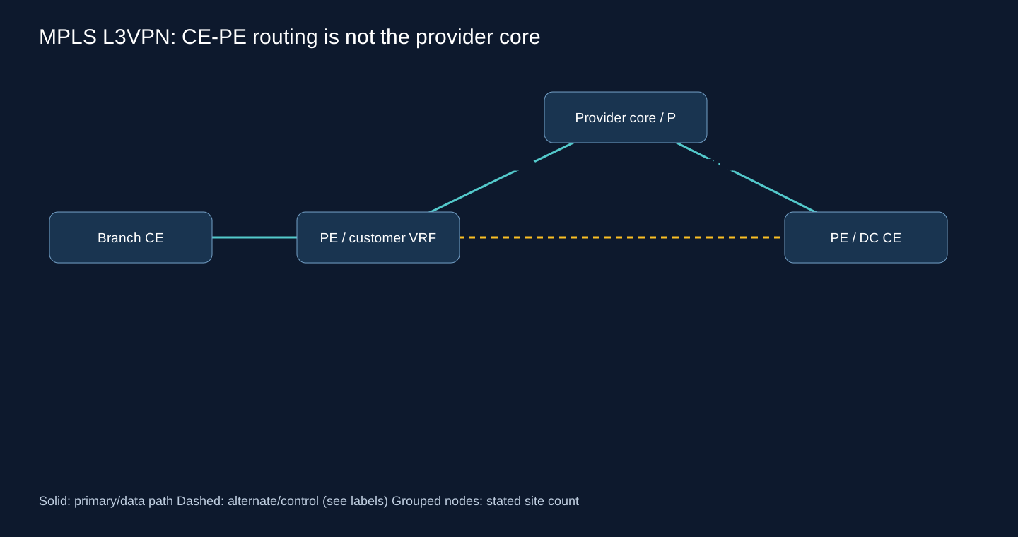
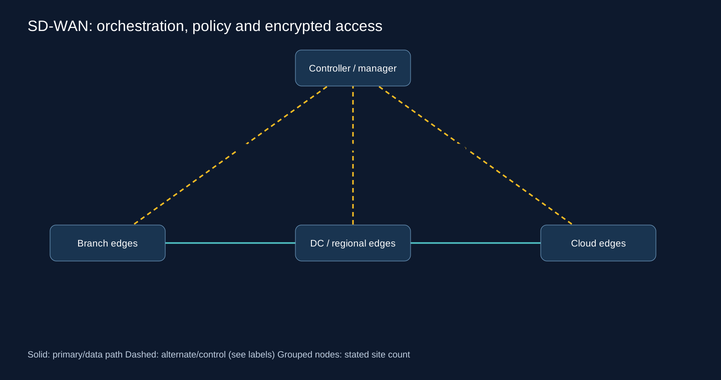
Questions engineers ask before implementation
Do 15 branches require dynamic routing?
No. Route churn, alternate paths and operating cost matter more than the count.
Does BGP encrypt a WAN?
No. Use an appropriate encrypted transport and restrict the BGP session separately.
Is OSPF over WireGuard always plug and play?
No. Design peer selection, multicast or unicast neighbors, allowed addresses and interface topology explicitly.
Were the labs executed on routers?
No. These are documentation-reviewed reproducible designs; expected results are acceptance criteria, not recorded measurements.
Official references and related Meet AJ guides
Start with the transport guide if the tunnel itself is not stable. Then use the routing lab and the failure runbook. Vendor manuals establish implementation behavior; RFCs establish protocol mechanisms. Before a purchase or production rollout, archive the exact release notes, hardware feature matrix and license/scale limits with the design. This article deliberately does not claim runtime validation of unsupported hardware or promise a fixed failover time.
Implementation documentation; protocol RFCs are linked beside their claims
MikroTik current routing manual, version 7.26
Cisco IOS XE 17.x routing implementation
Nexus 9000 NX-OS 10.5(x) feature restrictions
AWS Transit Gateway documentation
Azure VPN Gateway BGP reference
Related articles
WireGuard on MikroTik RouterOS 7
GRE, EoIP and IPIP transport design
MikroTik input/forward firewall hardening